Power, Caution – Measurement Computing WaveBook rev.3.0 User Manual
Page 65
WaveBook User’s Manual,
ch03C 6-21-99
WBK Expansion Options, WBK16 3-33
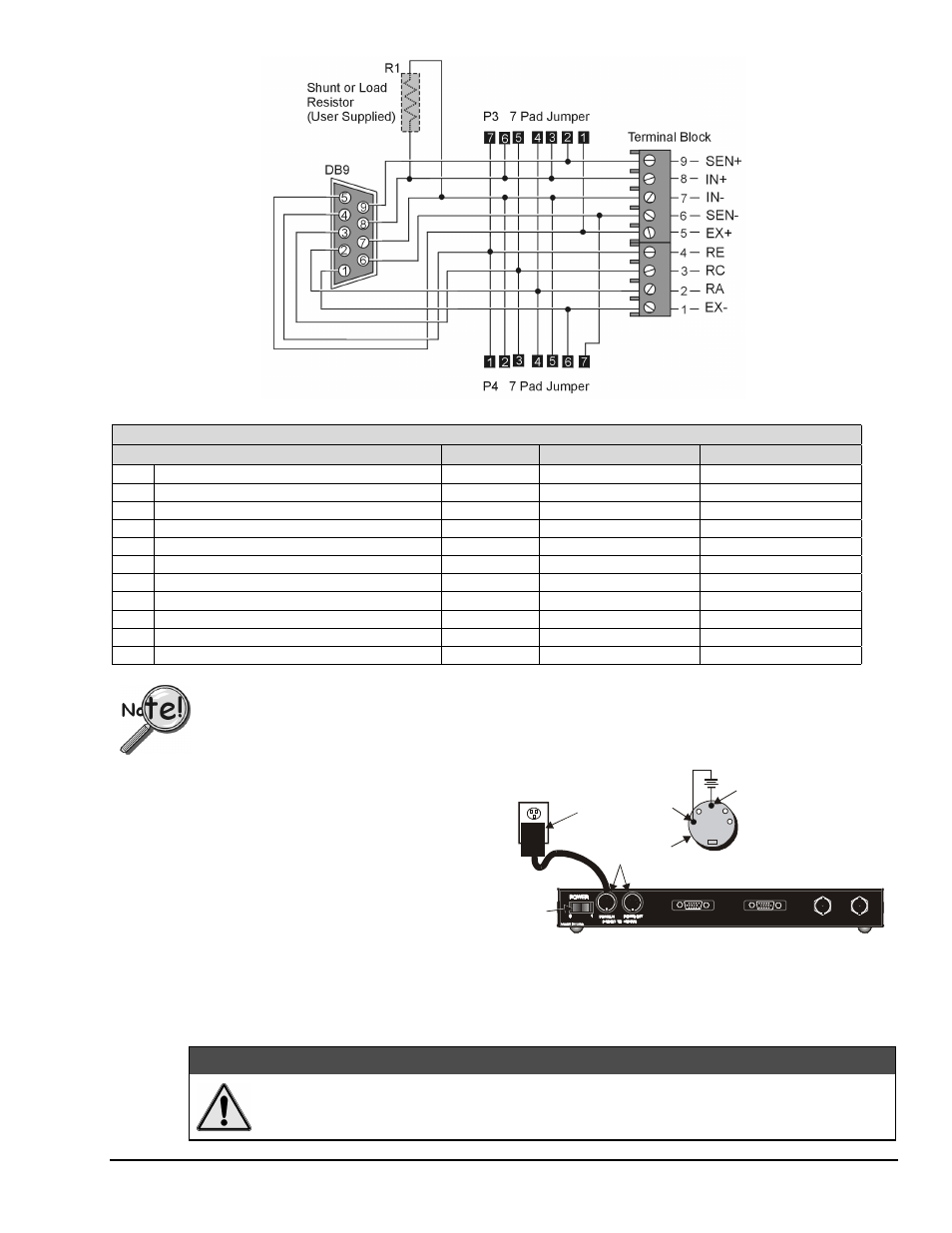
CN-189 Schematic
CN-189 DB9 Adapter for WBK16, Configuration Table
Function
P3
P4
Resistor Used in R1
1
Internal Excitation Sense
Short 1 and 2
Short 6 and 7
2
¼ Bridge Using (RA) 2-Wire
Short 3 and 4
3
¼ Bridge Using (RC) 2-Wire
Short 5 and 6
4
¼ Bridge Using (RE) 2-Wire
Short 6 and 7
5
High Gain Amp Ground Path (Short)
Short 5 and 6
6
High Gain Amp (Resistive) Ground Path (EXT)
Resistor between 5 and 6
7
High Gain Amp (RE) Ground Path (INT)
Short 1 and 2
8
High Gain Amp (RC) Ground Path (INT)
Short 2 and 3
9
High Gain Amp (RA) Ground Path (INT)
Short 4 and 5
10
Current Measurement (Differential)
Shunt resistor in R1
11
Differential Load Resistor
Load resistor in R1
For the functions listed in the preceding table, internal WBK16 configurations
still apply as indicated on pages 3-28 through 3-31.
Power
WBK16 requires an input voltage between +10
and +30 VDC. The DC source should be filtered
but not necessarily regulated—the TR-40U AC
power adapter is recommended for AC line
applications.
WBK16 may be powered with the supplied AC
adapter that plugs into any standard AC wall
outlet or from any isolated 10-30 VDC source of
at least 25 W (see figure). Before plugging unit
in, make sure the power switch is in the “0”
(OFF) position.
AC
Power
Adapter
AC
Power
Source
+V
+
GND
Power
Switch
Power Input
Connectors
WBK16 Rear Panel
10 to 30 VDC
WBK16 Power Connections
If you are using an AC power adapter, plug it into an AC outlet and attach the low voltage end to WBK16’s
DIN5 jack. If you are using another source of power, make sure leads are connected to the proper DIN5 terminals
as shown in the figure.
CAUTION
CAUTION
CAUTION
CAUTION
Do not exceed the 5 amp maximum DC current limit of the POWER IN and POWER OUT
DIN connectors.