Full-bridge configurations – Measurement Computing WaveBook rev.3.0 User Manual
Page 60
3-28 WBK16, WBK Expansion Options,
ch03B 6-23-99
WaveBook User’s Manual
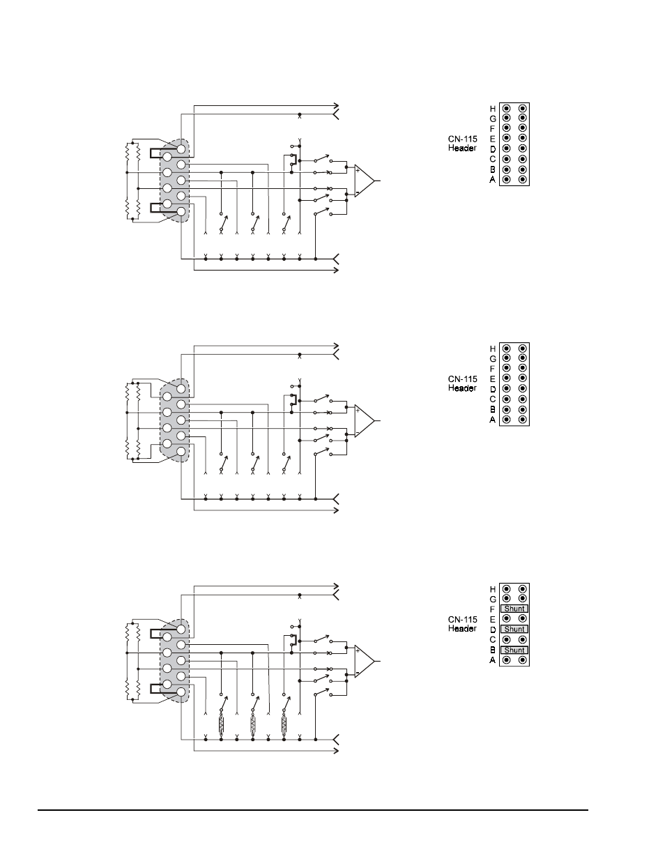
Full-Bridge Configurations
The full-bridge has four strain-variable elements and requires no bridge completion components. Quarter
and half-bridge resistors may be left installed. Any bridge resistance from 60 to 1000 ohms can be
accommodated.
Full-Bridge (+), Any Resistance from 60 to 1000 Ohms
IA
1
8
9
7
5
4
3
6
2
External
Bridge
DB-9
Input
Internal Bridge Completion
RA
RB
RC
RD
RE
RF
RG
RH
1
2
3
-Sense
+Sense
+Excitation
-Excitation
JN01
Switches
accessed
through
software
In this connection, excitation voltage is
regulated at the connector. This
configuration should only be used for
short cable lengths. Output polarity may
be altered by interchanging the (+) and (-)
input or by selecting the software invert
function.
Full-Bridge (+), with Remote Sense
IA
External
Bridge
DB-9
Input
Internal Bridge Completion
RA
RB
RC
RD
RE
RF
RG
RH
1
2
3
-Sense
+Sense
+Excitation
-Excitation
JN01
Switches
accessed
through
software
1
8
9
7
5
4
3
6
2
In this connection, excitation voltage is
regulated at the strain gage. This
eliminates errors due to cable losses and
is the preferred connection for longer
cables.
Full-Bridge (+), with B, D, or F Shunt
IA
External
Bridge
DB-9
Input
Internal Bridge Completion
RA
RB
RC
RD
RE
RF
RG
RH
1
2
3
-Sense
+Sense
+Excitation
-Excitation
JN01
Switches
accessed
through
software
1
8
9
7
5
4
3
6
2
The B, D, or F shunt resistor may be
software selected when installed as
shown. Output polarity during shunt
calibration will be automatically corrected
by software. The shunt resistor value will
typically be different for each value of
bridge resistance.