Caution – Measurement Computing WaveBook rev.3.0 User Manual
Page 58
3-26 WBK16, WBK Expansion Options,
ch03B 6-23-99
WaveBook User’s Manual
Shunt-Calibration Resistors. WBK16 provides three physical locations for internal shunt-calibration
resistors for each channel. Each shunt resistor is switched in from the EXCITATION (-) to the IN (+) of the
Instrumentation Amp by a FET switch to create a repeatable bridge imbalance. Internal resistance of the
circuit is about 1 k
Ω; the exact amount is automatically accounted for in the software. The software also
allows selection of the three shunt resistors ( B, D, F ). An internal inversion stage insures correct polarity
during the shunt calibration process; which arm is shunted is therefore irrelevant. Header positions Rb, Rd,
Rf correspond to the software shunt resistor selections of B, D, F.
For any balanced bridge, a resistance value can be placed in parallel with one element to create a
predictable imbalance and output voltage. This shunt-resistance value can be calculated by the following
equation, where V
out
is the differential output voltage of the gage.
Example:R
Shunt
= R
Bridge Arm
[ ( V
Excitation
/ 4 (V
out
)) - 0.5 ]
R
Shunt
= 350 [ ( 10 / 4(0.020)) - 0.5 ] = 43,575
Ω
Configuring the Bridge Completion Resistor Modules.
CAUTION
CAUTION
CAUTION
CAUTION
Be careful to avoid component damage while WBK16 enclosure is open. Always
remove bridge completion headers (adapter plugs) from the unit before soldering
resistors in the headers.
For each channel, the board has a 2×8 resistor socket with rows designated
A through H. The removable adapter plugs are included for soldering in the
resistors. Additional adapter plugs are available for convenient change-over of
alternate configurations. Resistor Ra is located nearest the front panel.
• Half-bridge completion resistors consist of Rg and Rh.
• Quarter-bridge completion resistors consist of Ra, Rc, and Re.
• Shunt resistors consist of Rb, Rd, and Rf.
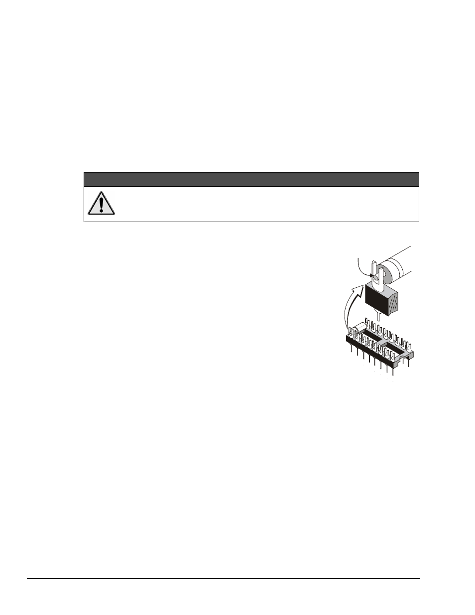
Inserting resistors directly into the socket makes an unreliable connection and is
not recommended. Solder resistors to the adapter plug as shown. Remove the
plug from the main board. To avoid damaging the pin alignment on the plug,
solder with minimal heat. After soldering, the resistor leads should be snipped
off close to the support.
Solder resistor lead
into support fork.
Soldering Resistors to
Adapter Plug