Connect signals – Measurement Computing WaveBook rev.3.0 User Manual
Page 10
QS-2 Quick Start,
6-24-99
WaveBook User’s Manual
2. Connect Signals
CAUTION
CAUTION
CAUTION
CAUTION
Voltages applied to WaveBook's BNC connectors must not exceed ±35 VDC.
Exceeding these specifications could result in equipment damage.
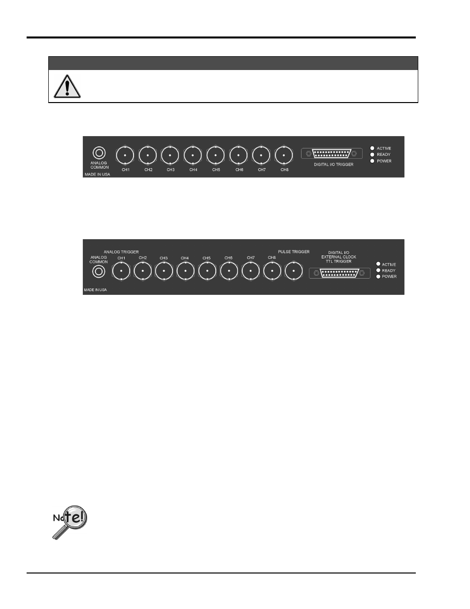
Signal connections are made on the WaveBook’s front panel. The front panels of the WaveBook/512 and
WaveBook/516 are similar. The /516 is taller and has one extra BNC connector (used for pulse trigger).
WaveBook/512 front panel has the following components:
• 1 Binding post for ANALOG COMMON reference
• 8 BNC connectors for analog inputs (analog channel 1 is also the low-latency analog trigger)
• 1 DB25F for DIGITAL I/O TRIGGER input
• 3 Status LEDs (ACTIVE, READY, POWER)
The WaveBook/516 front panel has the following components:
• 1 Binding post for ANALOG COMMON reference
• 8 BNC connectors for analog inputs (analog channel 1 is also the low-latency analog trigger)
• 1 BNC connector for PULSE TRIGGER input
• 1 DB25F for DIGITAL I/O including trigger input and EXTERNAL CLOCK input
• 3 Status LEDs (ACTIVE, READY, POWER)
WaveBook’s front panel has eight BNC connectors for analog inputs, a binding post for analog common,
and a DB25F connector for Digital I/O. Channel 1 is also used for low-latency analog triggering.
WaveBook/516 has an additional BNC connector for pulse trigger.
The center pin of each BNC connector is the high input and the outer shell is the low input. The inputs are
differential, the measured voltage being the difference between the high and low signal levels.
For proper operation, each analog input signal (high or low) must be within ±11 V of the WaveBook's
analog common level.
A few notes regarding ground, follow. Refer to Chapter 2 for more detailed information.
• When connected, WaveBook’s ANALOG COMMON is at the same potential as the host PC’s digital
ground.
• WaveBook’s analog channels are not isolated from the host PC.
• WaveBook’s power supply input is isolated from the rest of the WaveBook, including the
ANALOG COMMON and the PC’s digital ground.
For WaveBook [or WBK10/10H] to correctly measure analog signals, each signal must be within
±11 volts of ANALOG COMMON. Refer to Chapter 2 for detailed information.