Accelerometer tutorial – Measurement Computing WaveBook rev.3.0 User Manual
Page 45
WaveBook User’s Manual
WBK Expansion Options, WBK14 3-13
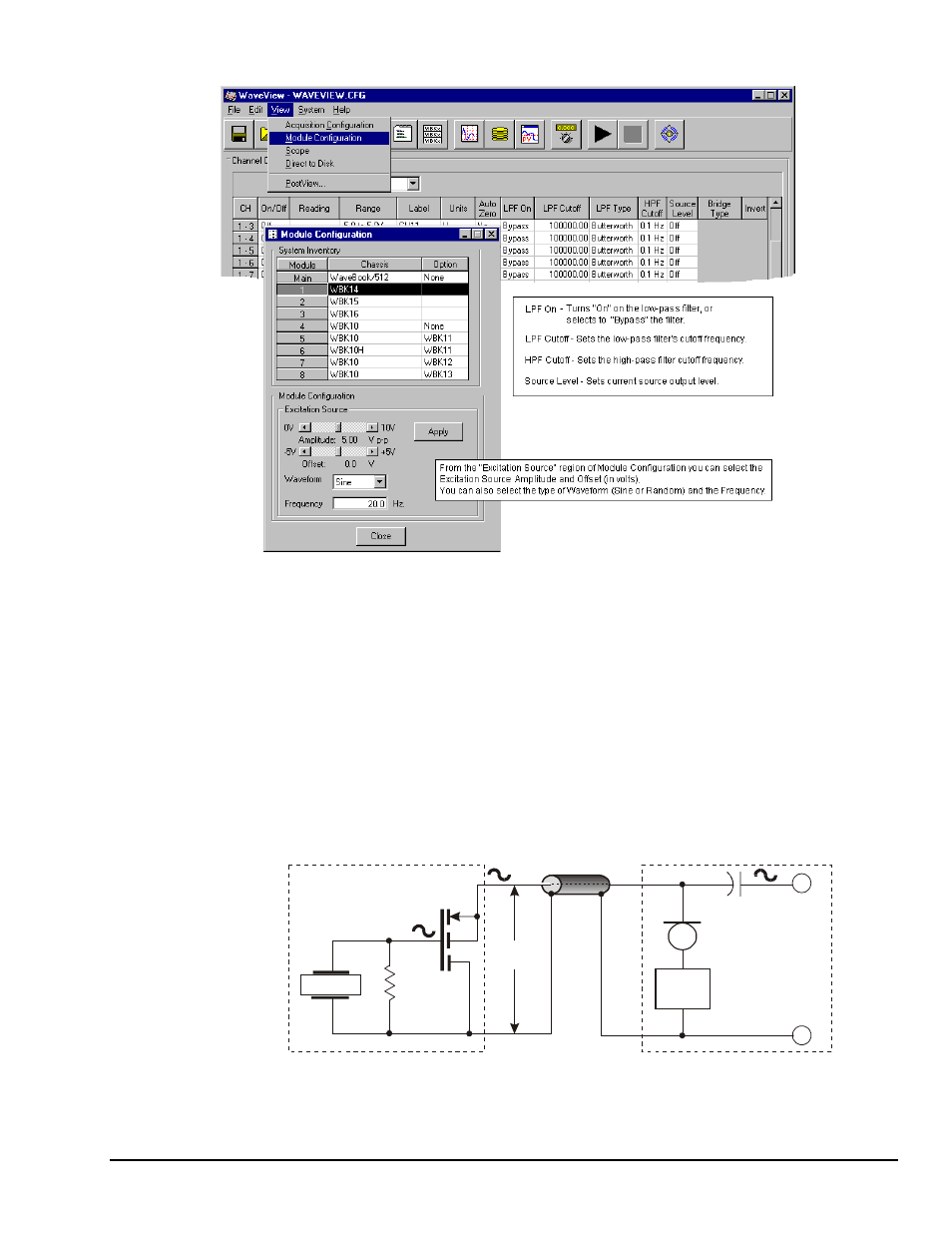
WaveView and Module Configuration Windows
Accelerometer Tutorial
A low-impedance piezoelectric accelerometer consists of a piezoelectric crystal and an electronic amplifier.
When stretched or compressed, the two crystal surfaces develop a charge variation that is related to the
amount of stress, shock, or vibration on the crystal. The amplifier outputs a corresponding signal and
transforms the sensor’s high impedance to a lower output impedance of a few hundred ohms. Besides
acceleration, such sensors can measure pressure and force.
The circuit requires only 2 wires (coax or twisted pair) to transmit both power and signal. At low
impedance, the system is insensitive to external or “triboelectric” cable noise. Cable length does not affect
sensitivity.
The figure shows a simple sensor-WBK14 connection. The voltage developed across R is applied to the
gate of the MOSFET. The MOSFET is powered from a constant current source of 2 or 4 mA and 27 volts.
Crystal
MOSFET
Sensor
Sensor to WBK14
Coaxial Cable
C
30 VDC
Power
R
GND
Amplifier
Input
Bias
Voltage
WBK14
-
+
Constant
Current
(2 or 4 mA)
Accelerometer Circuit