Software setup, Wbk11 - specifications – Measurement Computing WaveBook rev.3.0 User Manual
Page 39
WaveBook User’s Manual
WBK Expansion Options, WBK14 3-7
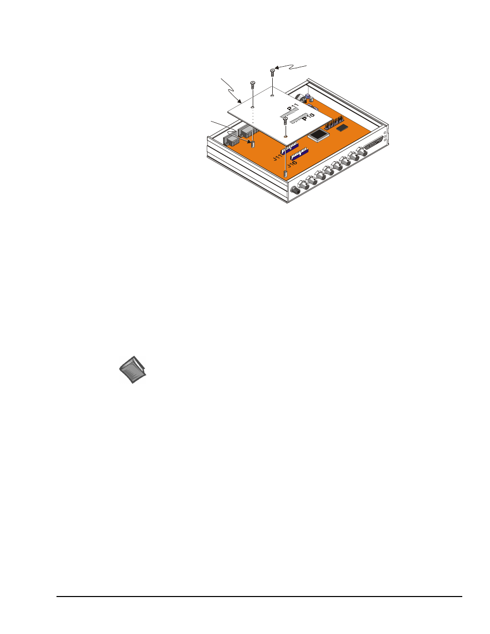
4. Locate the headers J10 & J11 on the main board, and remove the jumpers (if present).
Save the jumpers in the event the SSH board needs to be removed.
WBK11 Connection to WaveBook
Use 3 screws to secure
the WBK11 to the standoffs.
Standoff (×3)
WBK11 Board.
P11 connects to J11,
and P10 connects to J10.
5. Align WBK11 headers (P11 & P10) with the host board headers (J11 & J10), respectively.
6. Verify alignment of the board. An easy way is to check that the board’s screw holes are in line with the
standoffs.
7. Carefully push the WBK11 down until the connectors fully mate.
8. Using three screws, secure the WBK11 to the standoffs. Do not over-tighten.
9. Slide the top panel onto the unit, and secure it using the top panel screw.
10. Power up the unit.
11. Run WaveView to verify the channels connected to WBK11 have the new ranges.
Software Setup
You will need to set several parameters so WaveView can best meet your application requirements. For
software setup information, refer to the "Software Setup" section in Chapter 2: WaveBook Setup. For
detailed WaveView information, refer to Chapter 5: WaveView.
Reference Note: For more software setup information, refer to the "Software Setup"
section in chapter 2. For detailed WaveView information, refer to chapter 5.
WBK11 - Specifications
Specifications are provided in Appendix A.