Wbk16 - strain-gage module, Description, Channel selection – Measurement Computing WaveBook rev.3.0 User Manual
Page 54: Excitation source
3-22 WBK16, WBK Expansion Options,
ch03B 6-23-99
WaveBook User’s Manual
WBK16 - Strain-Gage Module
Description
WBK16 is an 8-channel strain-gage signal-conditioning module for the WaveBook system. Up to 8 WBK16
modules (64 channels) can be accommodated by the WaveBook and scanned at 1 µs/channel. Almost all
bridge configurations are supported via a bridge-completion network and software. High-gain differential-
amplifier applications are also supported. Software controls bridge configuration, gain, offset, excitation
voltage, polarity, filtering, and the calibration process.
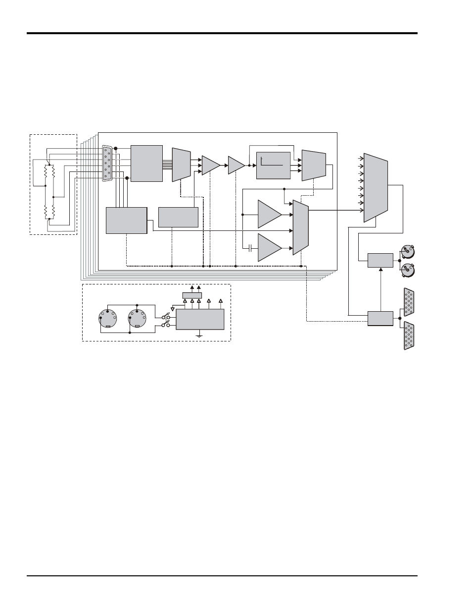
Refer to the following block diagram as needed while reading this section.
Channel 1 of 8
CH1
CH5
CH4
CH6
CH7
CH8
CH3
CH2
R
1
R
4
R
2
R
3
(+)EXC
(+)SENSE
(-)EXC
(-)SENSE
User Strain Gage
4-pole Low-
Pass Filters
a
f
LPF
Output
Selection
MUX
PGIA
PGA
Gain =
×1,10,
100,1000
Gain =
×1 to 20
Input
Config
& Cal
MUX
Bridge-
Completion
and
Shunt Cal
Network
Programmable
Excitation
Regulator with
Remote Sense
1Hz
High-
pass
Inverter
Amp
Programmable
Offset Voltage
Reference
DB-9
MUX
DB-15
DB-15
N
N
WaveBook Analog
Expansion Bus
WaveBook Digital
Expansion Bus
Analog
Interface
Digital
Interface
Serial Control Bus
WBK16 Block Diagram
Note: Strain-gage
configuration may
vary; see Bridge-
Completion
diagrams for
corresponding use
of DB-9 pinouts.
DC Power Input & Expansion
Power
Switch
DIN-5
DIN-5
+V
GND
Isolated
+5, +12, ±15 VDC
Power Supply
+5 V +12 V
Filters
+15 V
-15 V
Internal DC-DC Power Supply
Channel
Selection
MUX
Channel Selection
The eight independent channels are routed to the Channel Selection MUX (multiplexer) for output to the
WaveBook through the Analog Interface. The Digital Interface controls the channel-scanning process and
allows digital configuration of all channels through the WaveBook's Serial Control Bus.
Excitation Source
Excitation power is programmable from a dual source—channels 1 to 4 from one source and channels 5 to 8
from another source. Each channel has a separate regulator with a fold-back current limiter. Up to 85 mA is
provided at 10 V out, decreasing to 30 mA when shorted. This is sufficient current to operate 120
Ω gages
at any voltage. Programmable output voltages of 0, 0.5, 1, 2, 5, and 10 volts are available. Remote-sense
inputs are provided and should be connected at the strain gage for best accuracy. If they are not used, they
need to be jumpered to the excitation output at the connector. The remote-sense inputs are fully differential,
and may even be connected across the completion resistor to form a constant-current linearized
quarter-bridge configuration.