Wbk10/10h - expansion modules, Description, Front & rear panels – Measurement Computing WaveBook rev.3.0 User Manual
Page 34
3-2 WBK10/10H, WBK Expansion Options
WaveBook User’s Manual
To meet CE requirements, PVC dust caps (p/n CN-96) must cover all unused BNC connectors. When dust
caps are not in place, special coaxial cables (with insulated end-connectors and rubber O-rings) must be
used. Note that part number 418-0800 includes two cables (with shielded BNC connectors at each end),
and four insulating O-rings.
Properly installed connectors and dust caps ensure the metallic surfaces of the connectors are not exposed to
undesirable electrical charges.
WBK10/10H - Expansion Modules
Description
The WBK10/10H expansion modules provide the WaveBook with 8 additional differential analog inputs,
each equipped with a programmable gain instrumentation amplifier (PGA). (The two models are the same
except for analog input ranges.) The WaveBook and WBK10/10H have a built-in expansion bus. Up to
eight WBK10/10Hs can be cascaded together for a system capacity of 72 differential channels. Each
WBK10/10H is also capable of supporting a WBK11, WBK12, or WBK13 option card.
Physically, the WBK10/10H is the same size (8½×11 in) as the WaveBook for convenient mounting. A
splice plate kit allows multiple units to be stacked vertically. Screw-on handles are available for portable
applications.
N
N
8-channel
Differential
MUX
Unipolar/Bipolar
Level Shifter
Offset Adjust
Differential
Amplifier
EEPROM
OUT
IN
Expansion
Unit Control
Control and
Timing Circuit
Expansion
Signal
Enable
PGA
-
+
DC/DC
Converter
10 to 30 VDC Input power
from AC adapter, DBK30A,
DBK34, or 12-V car battery, etc
Power Supply
+5
- 5
+15
- 15
Fuse
ON/OFF
Switch
DIN5s can be
daisy-chained
N
8
Differential
Analog
Inputs
Buffers
Channel 1 of 8
7
7
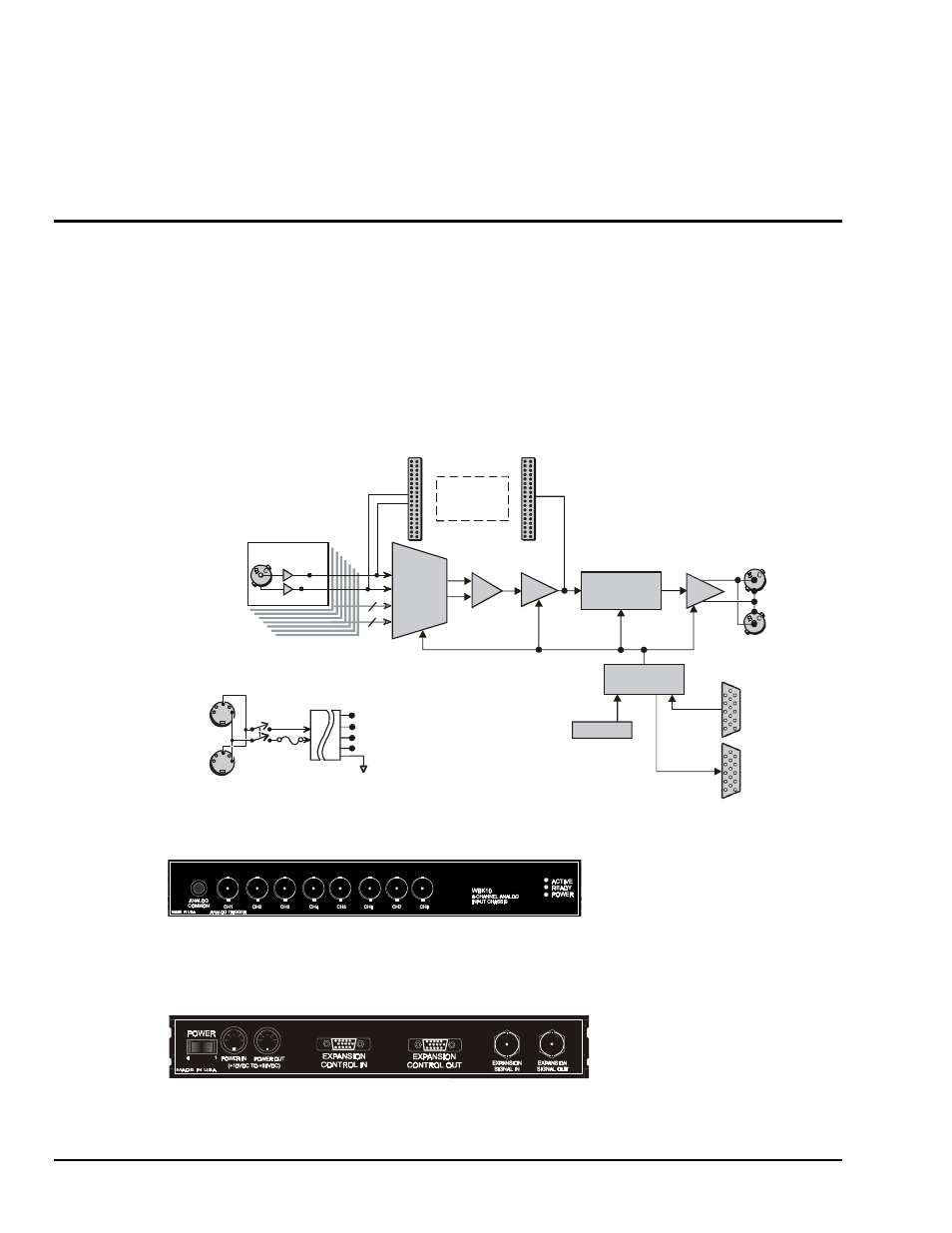
WBK10 Block Diagram
Optional
WBK11
J10
J11
Front & Rear Panels
The front panel of the WBK10/10H has the following connectors and indicators:
• 1 Analog Common binding post for reference.
• 8 BNC connectors for analog inputs. Channels are labeled 1 through 8. Note that additional WBK10/10H unit
channels are identified by higher channel numbers as discussed in upcoming text.
•
3 Status LEDs (Active, Ready, Power).
The rear panel of the WBK10/10H has a power switch and the following connectors:
• 2 circular 5-pin DIN5 connectors for Power-in and Power Pass-Through.
• 1 HD-15M expansion control input.
• 1 HD-15F expansion control output.
•
2 BNC connectors for analog expansion, in and out.