Wavebook/512, Analog signal processing, Digital i/o signal processing – Measurement Computing WaveBook rev.3.0 User Manual
Page 139: Book/512… 8-5, Ng…… 8-5, Signal processing
WaveBook User’s Manual.
6-24-99
Theory of Operation 8-5
Signal Processing
WaveBook/512
Analog Signal Processing
Each of up to 72 analog inputs are amplified and level-shifted to provide 8 input ranges (or 14 with the
WBK11 SSH card). The amplified signals are digitized to at least 11.98 bit resolution (4050 counts) with a
12-bit A/D converter and then corrected to 11-bit accuracy (not counting the sample-to-sample noise) by the
DSP. The total system noise is less than 1-bit RMS at a gain of ×10.
The analog data format is a signed 16-bit number with -32768 (8000h) representing the minimum input
voltage, 0 representing midscale, and 32752 (7FF0h) representing the maximum input voltage. The four
least significant bits are not zero, but instead include fractional bit information from the digital calibration
process. These bits are discarded, after rounding, if the samples are packed for transfer to the PC. If data
packing is not used, then these bits are preserved.
Digital I/O Signal Processing
WaveBook/512 supports 8 high-speed digital inputs. When data acquisition is not in-process, the port can
also be used as a 32-address, general-purpose I/O port.
WaveBook/512 digital I/O port writes and reads 8-bit bytes to and from 32 addresses. The pipelined,
DSP-based design of WaveBook restricts the digital I/O port to the following types of access:
• During Acquisition: Read a byte from the digital I/O port at address 0 as the first element in the scan.
• With Acquisition Stopped: Read and write bytes at any address under the command of the host PC.
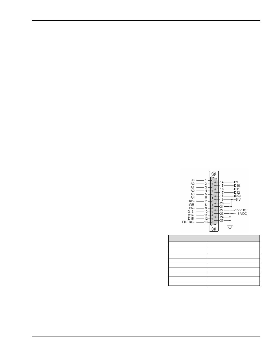
Digital I/O Connection (WaveBook/512 and /512H Only)*
With the WaveBook/512 series, the following signals are present on
the DB25F high-speed digital I/O connector.
• 8 Digital I/O Lines (D8 – D15)
• 5 Address Lines (A0 –A4)
• Active-low Digital I/O Enable output (EN-)
• Active-low Digital I/O Write Strobe (WR-)
• Active-low Digital I/O Read Strobe (RD-)
• TTL Trigger Input (TTLTRG)
• +15 V (pin 23), -15 V (pin 22), 50 mA max. (each)
• two +5 V power (pins 19 and 21), 250 mA max. (total)
•
three Digital Grounds (pins 20, 24, and 25)
Digital I/O Connections, WaveBook/512*
D8-D15
Digital I/O data lines
A0-A4
Digital I/O address lines
EN-
Active-low digital I/O enable
To sample just 8 digital input signals, connect them directly to the
digital I/O data lines. D15 is the most significant bit, and D8 is the
least. The address lines, the read and write strobes, and enable signal
may all be left disconnected.
RD-
Active-low read strobe
WR-
Active-low write strobe
TTLTRG
TTL trigger input
+5 VDC
250 mA maximum
+15,-15 VDC
50 mA maximum (each)
*Note: This pinout can be used for WaveBook/516, providing the unit is in the 8-bit
mode (instead of 16-bit). If using this pinout for WaveBook/516 (in 8-bit
mode), pin 20 will be assigned to external clock input (instead of digital
ground).
Digital Grounds
Pins 20, 24, and 25