Input channel configuration, Onfiguration…… 5-9 – Measurement Computing WaveBook rev.3.0 User Manual
Page 103
WaveBook User’s Manual,
6-24-99
WaveView 5-9
Input Channel Configuration
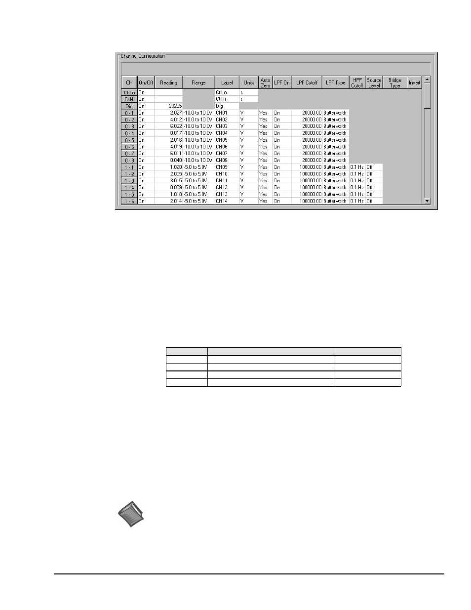
Channel Configuration Spreadsheet
This spreadsheet allows the analog input channels and/or digital channel to be configured and displayed.
The Dig row (top row, when the slide all the way up) is for the high-speed digital input channel. The Dig
row is visible in the figure on page 5-6. Note that the number of rows may vary depending on your system.
The various columns contain the configuration information for each channel. Some columns allow blocks of
cells to be changed simultaneously; others allow only one cell to be changed at a time. Some columns may
be static and cannot be altered. Clicking a column header will select the entire column if applicable.
Column descriptions follow.
• CH. The channel number column labeled CH is static and cannot be altered. This column identifies the
analog (or digital) input channel to be configured in that row. This number includes all channel
numbers from the WaveBook and any attached expansion chassis (WBK10/10H, WBK14, WBK15,
and WBK16). With two WBK10 or WBK10H expansion chassis, the channels would be numbered as
follows:
CH
Description
Default Label
Dig
WaveBook Digital Channel
Dig
0-1 to 0-8
WaveBook Analog Channels
CH01 to CH08
1-1 to 1-8
First Expansion WBK10/10H Channels
CH09 to CH16
2-1 to 2-8
Second Expansion WBK10/10H Channels
CH17 to CH24
• On/Off. This column allows you to include or exclude a channel from the scan list. When a cell is
selected, the selection box above the spreadsheet allows “On” or “Off” to enable or disable the channel.
Double-clicking a cell in this column will toggle the channel status. The Make All Channels Active and
Make All Channels Inactive menu items under the Edit menu can be used to globally change all
channels to either “On” or “Off.”
• Reading. Not user configurable. This column displays values of enabled channels.
Range. This column allows you to set the gain and polarity for the selected channel(s). Single-clicking
the mouse in any of the analog channel Range boxes brings up the "Select Range" selection box.
Double-clicking on a cell will cycle through the available ranges. The Range selections have no effect
on the Digital Input channel.
Reference Note:
Ranges, including those provided by the use of option cards and expansion modules, are
presented in Appendix A.
• Label. This column contains a descriptive name for the input channel. By default, the label is similar to
its channel number, but the name can be any 8 characters. Single-click on the desired cell, and type in
the desired name. This column does not have a selection list above the spreadsheet and does not allow
selecting multiple blocks of cells.