Optimizing fiber laser cut quality, Surface of a laser cut, Optimizing fiber laser cut quality -40 – Hypertherm HyIntensity Fiber Laser Rev.3 User Manual
Page 148: Surface of a laser cut -40
setup and OperatiOn
3-40
Hypertherm Fiber Laser
Instruction Manual – 807090 Revision 3
Optimizing fiber laser cut quality
This section describes how to adjust the fiber laser system to optimize cut quality.
Note: This revision of the manual includes cutting tips for 6 mm mild steel. Future revisions will include additional thick-
nesses of mild steel as well as aluminum and stainless steel.
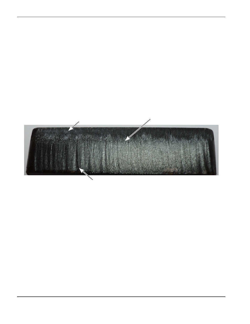
Surface of a laser cut
Laser-cut parts always exhibit a characteristic grooved pattern on the cut edge. These grooves are known as cut lines,
or striations, and do not affect the edge quality when the proper cutting parameters and material are used. These cut
lines can be further defined as upper and lower cut lines. The upper cut lines exist on the laser beam entrance side and
the lower cut lines exist on the laser beam exit side of the cut edge. The upper and lower cut lines are separated by what
is known as the boundary layer. The picture below shows an acceptable cut edge that is magnified to clearly show the
upper and lower cut lines as well as the boundary layer.
Notice that the upper cut lines are shallower and more periodic than the lower cut lines. The uniqueness of these cut
Upper cut lines
Lower cut lines
Boundary layer
lines is valuable for identifying and correcting cut quality problems. Cut lines can indicate incorrect cutting parameters
such as focus position, assist gas pressure, cut height, and cut speed.