Operating the laser head controller, Operating the laser head controller -11 – Hypertherm HyIntensity Fiber Laser Rev.3 User Manual
Page 119
setup and OperatiOn
HyIntensity Fiber Laser
Instruction Manual – 807090 Revision 3
3-11
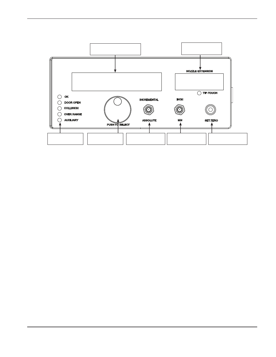
Operating the laser head controller
1. Laser head LEDs:
• OK: Green indicates that the laser head controller has power and is operational.
• Door Open: Red indicates that the lens door is open, the cutting lens is not installed or the collimator is not
installed. When this fault is active the beam is disabled.
• Collision: Red indicates that a head collision is detected. When this fault is active the beam is disabled.
• Over Range: Red indicates that the nozzle is greater than 10 mm from the plate.
• Auxiliary: Red indicates an assist gas low pressure fault.
Note: The collimator is sensed by a proximity sensor at the top of the cutting head. The proximity sensor has an orange
indicator light that should be illuminated when the collimator is installed. See Operating the laser head for
more details.
2. The laser head controller LCD display shows various system information.
3. The rotary selection knob is used to navigate LCD screens and edit parameters. Rotate the knob to move from
one parameter to another on the screen and push the knob to select the parameter that needs to be adjusted.
4. The nozzle extension mode switch selects between incremental and absolute position display for the nozzle
extension. The Absolute/Incremental switch is used to change the way the display shows the position of
the nozzle extension. When the switch is in the Absolute position the nozzle extension displays the absolute
position of the nozzle extension. When the switch is in the Incremental position the nozzle extension value is a
positive or negative incremental position from the point that the set zero button was pressed.
5. The Inch/Metric selection switch is used to set the display to show the nozzle extension position in inches
or millimeters.
• When the switch is in the INCH position the current nozzle extension is displayed in inches.
• When the switch is in the MM position the current nozzle extension is displayed in millimeters.
6. The nozzle extension LED display shows the position of the nozzle extension.
7. The nozzle extension set-to-zero switch is used to set the zero position of the nozzle extension when using the
Incremental mode.
1. Indicator LEDs
2. System LCD display
6. Nozzle extension
LED display
3. Selection knob 4. Nozzle extension
mode switch
5. Inch/Metric
selection switch
7. Nozzle extension
set zero switch