3 piic data interface slots – Comtech EF Data CDM-750 User Manual
Page 59
CDM-750 Advanced High-Speed Trunking Modem
Revision 2
Rear Panel Connections
MN-CDM750
3–13
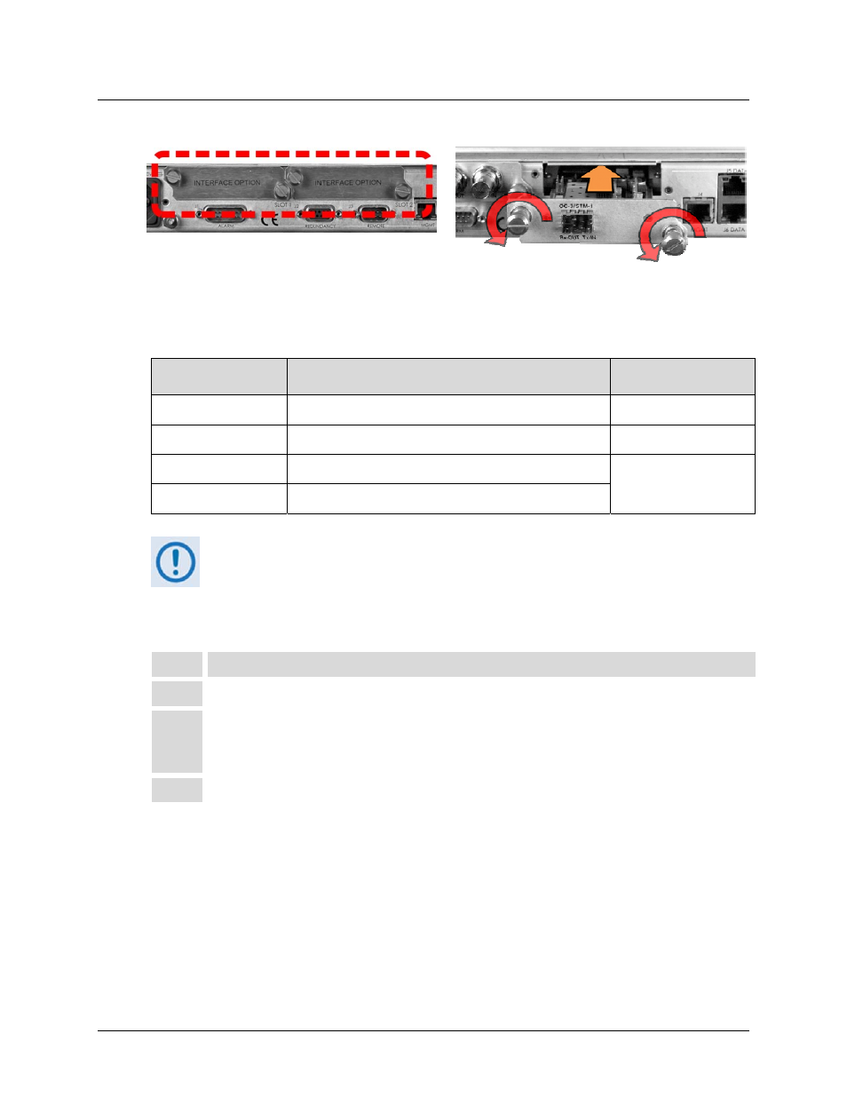
3.2.3.3 PIIC Data Interface Slots
Figure 3-5. Typical PIIC Module Installation
The CDM‐750 rear panel features two slots that accommodate optional PIIC (Plug‐in Interface
Card) data modules. The available PIIC modules are as follows:
CEFD Kit / Assembly
Description
For Details See
Appendix B Sect.
PL-0000795
G.703 ‘BNC’ E3/T3/STS-1 PIIC Module
B.2.1
KT-0000255
SFP STM-1 Copper ‘BNC’ PIIC Module
B.2.2
KT-0000256
SFP OC-3 Single Mode PIIC Module
B.2.3
KT-0000257
SFP OC-3 Multi Mode PIIC Module
Additional PIIC module data options (ASI, HSSI, etc.) will become available upon
request.
Follow these steps to install the optional PIIC module(s) (Figure 3‐5):
Step
Task
1
Remove the PIIC slot blank panel(s) by loosening the captive thumbscrews.
2
Install the data module(s) into position using the chassis’ internal card guides. Slide
the module straight back into the chassis until the module is firmly plugged into the
mating receptacle(s).
3
Secure the captive thumbscrews of the module(s).