3 base unit connectors, 4 test functions, 5 modulator (dual if) – Comtech EF Data CDM-750 User Manual
Page 36
CDM-750 Advanced High-Speed Trunking Modem
Revision 2
Introduction
MN-CDM750
1–12
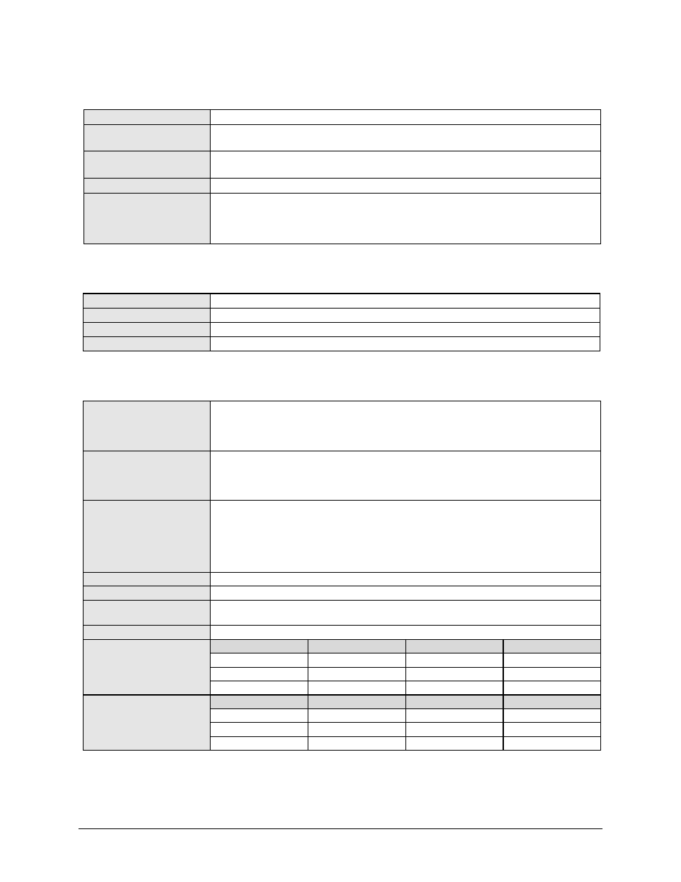
1.4.3
Base Unit Connectors
Alarm Connector
DB-15 male: Form C; Tx, Rx and unit faults; External Tx Carrier Off; IQ test point
Unit Management
• DB-9 male with EIA-232 and RS 485 2W/4W
• RJ-45 Ethernet (Maximum Ethernet packet size 1536 bytes including Ethernet header & CRC)
Tx & Rx IF Connectors
• 70/140 MHz: BNC
• L-Band: Type ‘N’ female
L-Band Monitor
Type ‘SMA’ female
Traffic Data Interface
• 2X RJ45 10/100/1000 BaseT Ethernet
• 1X Optical Gigabit Ethernet (optional)
Note: All Data Gig-E interfaces have a maximum Ethernet packet size of 1632 bytes including Ethernet
header & CRC
1.4.4
Test Functions
Data Test Pattern
2^10-1, 2^15-1 and 2^23-1 compatible with BERT on applicable interfaces
CW
Modulation disabled and CW signal is transmitted
SSB Carrier
Provides suppressed carrier and suppressed sideband
Loopback
Full Duplex only
1.4.5
Modulator (Dual IF)
70 / 140 MHz
Impedance / Connector
Output
Power
Power
Accuracy
50 to 180 MHz in 100 Hz steps, maximum symbol rate is within IF limits
75
Ω / BNC Female. Return Loss ≥ 18 dB
0 to -20 dBm, 0.1 dB steps (70/140 MHz)
±0.5 dB of nominal at 25
°C. Within ±0.5 dB from 25°C value at same frequency
L-Band
Impedance / Connector
Output
Power
Power
Accuracy
950-2150 MHz in 100 Hz steps, modulator maximum symbol rate is within IF limits
50Ω, Type N Female. Return Loss ≥ 15 dB
-5 to -40 dBm, 0.1 dB steps
±0.5 dB of nominal at 25
°C, ±0.5 dB from 25°C value at same frequency
L-Band Monitor
Port Impedance
Port Connector
Port Level
Port Isolation
Monitor Frequency
50
Ω (available in modulator only or modem configuration)
SMA Female
-27 dBm ± 3dBm
20 dB min
70/140 MHz: 900+70/140 MHz, L-Band: same.
Harmonics and Spurs
< 60 dBc/4kHz, modulated carrier. Excludes spectral mask area.
External Tx Carrier Off
TTL Low signal
Quadrature Phase Error and
Amplitude Imbalance
Sideband 35 dB below unmodulated carrier
Spectral Inversion
Normal or Inverted
Carrier Phase Noise
Frequency Offset
dBc/Hz
Frequency Offset
dBc/Hz
10 Hz
-36
10 kHz
-86
100 Hz
-66
100 kHz
-96
1 kHz
-76
1 MHz
-96
BUC 10 MHz Reference
Frequency Offset
dBc/Hz
Frequency Offset
dBc/Hz
10 Hz
-105
10 kHz
-148
100 Hz
-125
100 kHz
-150
1 kHz
-138