F.4 cdm-750 ethernet overview, F.4.1 ethernet interfaces – Comtech EF Data CDM-750 User Manual
Page 289
CDM-750 Advanced High-Speed Trunking Modem
Revision 2
Appendix F
MN-CDM750
F–3
F.4
CDM-750 Ethernet Overview
F.4.1 Ethernet Interfaces
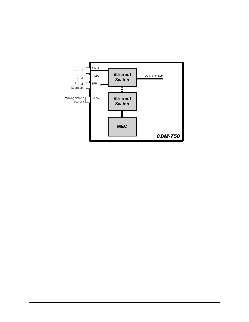
Figure F-2. CDM-750 Ethernet Architecture Design
Figure F‐2 shows the internal Ethernet architecture for the CDM‐750. The CDM‐750 modem has
two built‐in 10/100/1000 BaseT Ethernet Ports and an optical Gigabit Ethernet port (for use with
the optional Optical Ethernet SFP module – see Chapter 3. REAR PANEL CONNECTIONS)
connected to a single internal Ethernet Layer 2 Switch. Port configuration and statistics are
available on a per‐port basis.
This configuration allows for multiple customer Ethernet interfaces. The 10/100BaseT
management port is connected to a switch that interfaces optionally with the data traffic switch
and the M&C controller. Normally, the management port is configured so that management
traffic is physically separated from the data traffic ports. However, it is possible to enable
operation so that management traffic may pass with the data through the data traffic ports and
WAN interface.
It should also be noted that additional care must be taken to avoid Ethernet Networking Loops as
defined in Sect. F.3.1. Specifically, the network operator must make sure to avoid connecting
multiple ports of the CDM‐750 to the same external Ethernet switch, as shown in Figure F‐3.