2 rear panel, 1 rear panel standard features – Comtech EF Data CDM-750 User Manual
Page 33
CDM-750 Advanced High-Speed Trunking Modem
Revision 2
Introduction
MN-CDM750
1–9
1.3.3.2 Rear Panel
PROPER GROUNDING PROTECTION IS REQUIRED. The equipment must be connected
to the protective earth connection at all times. It is therefore imperative that the unit
is properly grounded, using the ground stud provided on the unit rear panel, during
installation, configuration, and operation.
• Sect. 3.2 CDM‐750 Cabling Connections
• Sect. 3.3 CDM‐750 Grounding and Power Connections
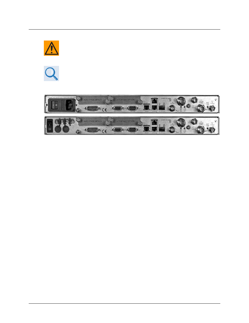
External cables are attached to connectors provided on the rear panel of the unit (Figure 1‐4).
(Top) Standard AC Unit
(Bottom) Optional 48V DC Unit
(FUTURE)
Figure 1-4. CDM-750 Rear Panel View
1.3.3.2.1 Rear Panel Standard Features
The unit provides the following standard interfaces:
Data Interfaces:
• (2X) 10/100/1000 BaseT Gigabit Ethernet RJ‐45 Interface: J5|DATA and J6|DATA ports for
Ethernet traffic.
• (1X) 10/100 BaseT Fast Ethernet RJ‐45 Interface for Ethernet‐based management and
control purposes (HTTP/Web and SNMP):J4|MGMT port.
• (1X) DB‐9F EIA‐232 connector for serial remote control: J3|REMOTE port.
• (1X) DB‐15M connector for Form C unit alarms, analog Es/No, and Tx Mute: J1|ALARMS
port.
IF Interfaces:
• (2X) Type ‘N’ female connectors for 50Ω L‐Band (950 to 2150 MHz) input/output: J9 | L‐
Band Rx In and J12 | L‐Band Tx Out