C.2 background – Comtech EF Data CDM-750 User Manual
Page 238
CDM-750 Advanced High-Speed Trunking Modem
Revision 2
Appendix C
MN-CDM750
C–2
C.2
Background
The CDM‐750 system is based on DVB‐S2 standards. The DVB standardized a suite of 28
ModCods that work over an Es/No range of ‐2.3 dB to 16.0 dB (ideal). They have also defined
much of the system for both ACM and a related feature called Variable Coding and Modulation
(VCM)
. DVB‐S2 did not specify the means of passing necessary information between system
components, so the ACM schemes adopted by different manufacturers are generally not
interoperable.
During ACM operation, control parameters between modems are transferred over the satellite
link along with user traffic in what is usually referred to as Inband Signaling. DVB‐S2 also
describes an ACM method using “out‐of‐band” ACM controllers (per EN 302 307 Annex D.1) that
is not supported with the CDM‐750.
The CDM‐750 supports duplex ACM operation between a pair of modems in a point‐to‐point
link. While point‐to‐multipoint operation is not currently supported, the modem’s physical layer,
software, and overall architecture are designed to allow future expansion.
In ACM mode, the symbol rate remains constant, and the modulation and coding (ModCod in
DVB‐S2 terms) changes to preserve the data integrity. Most links are designed with enough Es/No
margin to provide error free performance under faded conditions when there is higher
attenuation in the uplink or downlink path to/from the satellite.
Depending on the geographical region and link budget criteria, faded conditions can occur less
than 1% of the time. In such as case the operating Es/No of the link is higher than needed for more
than 99% of the year. ACM takes advantage of this link margin by increasing the ModCod during
unfaded conditions allowing the link to operate at a higher data rates during these periods. A
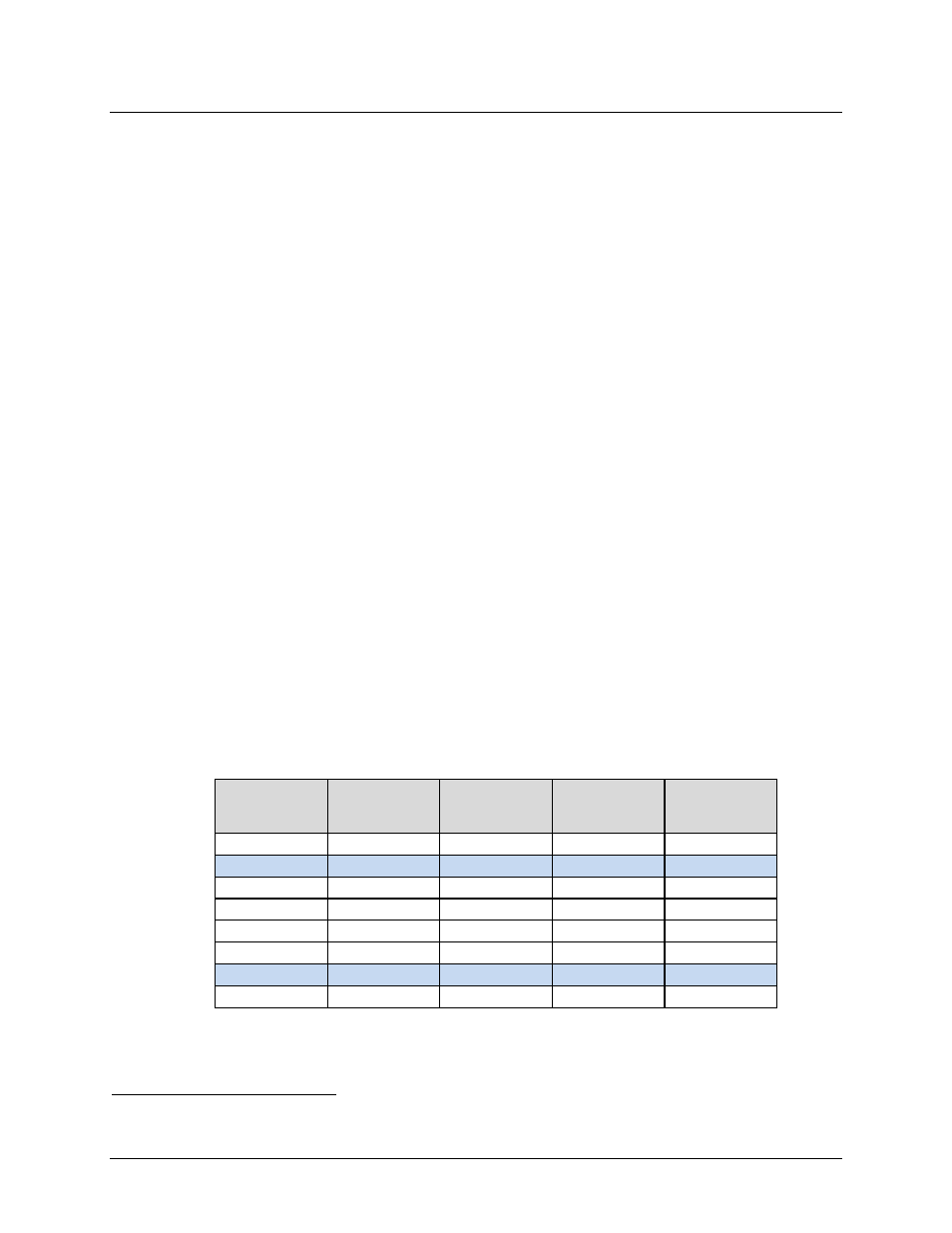
simplified example illustrates the point. Table C‐1 shows the several ModCods, the Spectral
Efficiency (SE), and Es/No for the CDM‐750 assuming Normal FEC Frame (64,800 bits).
Table C-1. ACM Example for Standard FECFrame (64,800 bits)
ModCod #
ModCod
Spectral
Efficiency
Pilots ON
Guaranteed
Es/No (dB)
Data Rate
(Mbps) at 20
Msps
4
QPSK 1/2
0.9653
1.4
19.31
5
QPSK 3/5
1.1600
3.7
23.20
6
QPSK 2/3
1.2908
3.4
25.82
7
QPSK 3/4
1.4521
4.6
29.04
8
QPSK 4/5
1.5494
5.1
30.99
9
QPSK 5/6
1.6153
5.6
32.31
10
QPSK 8/9
1.7244
6.7
34.49
11
QPSK 9/10
1.7460
6.8
34.49
Example: If a link is designed to operate at an Es/No of 3.7 dB during a 3.0 dB fade, the 3.0 dB
fade is commonly referred to as link margin . When fade conditions are not present, the link
1
VCM operation does not provide any advantage in a point to point link and therefore is not supported