6 demodulator (dual if) – Comtech EF Data CDM-750 User Manual
Page 37
CDM-750 Advanced High-Speed Trunking Modem
Revision 2
Introduction
MN-CDM750
1–13
1.4.6
Demodulator (Dual IF)
70 / 140 MHz
Impedance / Connector
Input
Power
Maximum Composite Level
50 to 180 MHz in 100 Hz steps
75
Ω / BNC Female. Return loss 15 dB min
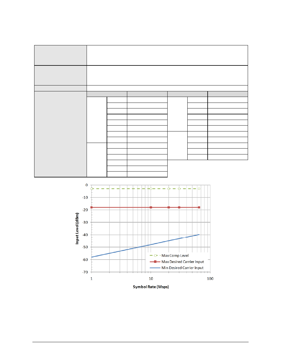
Desired Carrier = -58 + 10Log(Symbol Rate in Msps) dBm min and -18 dBm max – See Fig. 1-5
The lesser of +20 dBc – 10log(Symbol Rate in Msps) or -3 dBm
L-Band
Impedance / Connector
Input
Power
Maximum Composite Level
950-2150 MHz in 100 Hz steps, demodulator
50Ω, Type N Female. Return loss 10 dB min
Desired Carrier = -65 + 10log (Symbol Rate in Msps) dBm min and -25 dBm max – See Fig. 1-6.
The lesser of +30 dBc – 10log(Symbol Rate in Msps) or -10 dBm
Acquisition Range
±150 KHz ≤ 5 Msps, ≤ 500 KHz > 5 Msps.
Es/No performance as per
DVB-S2 QEF PER 1E-7
Specifications (Normal
Frames)
[Applies with one like
modulated carrier spaced 1.3 x
Symbol Rate and 10 dB higher
than the desired carrier.
Conditions are 30 Msps and
Pilots ON]
Mod/Cod
Es/No
Mod/Cod
Es/No
QPSK 1/2
1.4
16-APSK
2/3
9.9
3/5
2.7
3/4
11.2
2/3
3.4
4/5
12.0
3/4
4.6
5/6
12.4
4/5
5.1
8/9
13.8
5/6
5.6
9/10
14.0
8/9
6.7
32-APSK
3/4
14.6
9/10
6.8
4/5
15.8
8-PSK 3/5
6.4
5/6
16.6
2/3
7.4
8/9
19.1
3/4
8.5
9/10
19.5
5/6
10.0
8/9
11.3
9/10
11.6
Figure 1-5. 70/140 MHz Input Level vs. Symbol Rate