Comtech EF Data CDM-750 User Manual
Page 263
CDM-750 Advanced High-Speed Trunking Modem
Revision 2
Appendix D
MN-CDM750
D–5
D.4
System Functionality and Operational Considerations
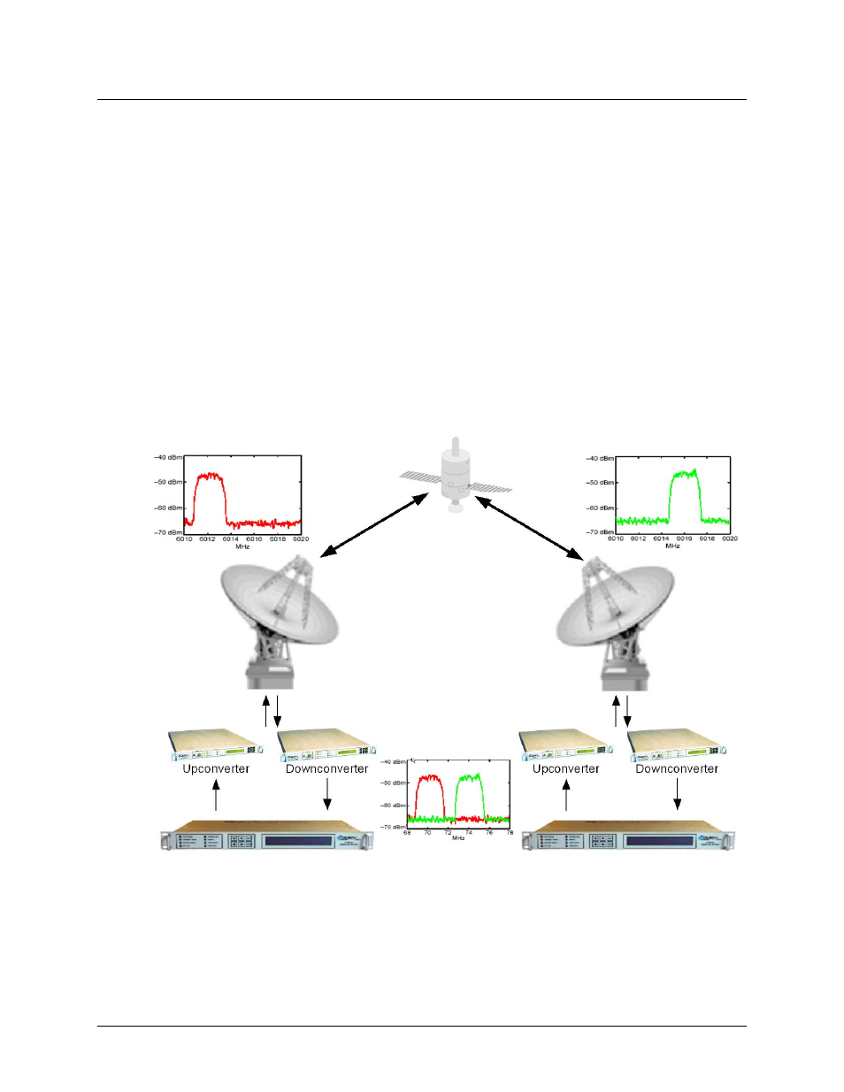
Figure D‐2 illustrates a conventional, full duplex satellite link where two carriers are placed in
non‐overlapping channels. Figure D‐3 shows the same link using CDM‐750s equipped with the
CnC option. Note now that, with CnC used, only 50% of the bandwidth is being used, as both
carriers are occupying the same bandwidth.
The transponder downlinks the composite signal containing both carriers on the same band to
the CDM‐750 which then translates the signal to near baseband where it can be filtered
(decimated) and then processed as a complex envelope signal. The CDM‐750 then suppresses
the version of the near end carrier on the downlink side and then passes the desired carrier to
the demodulator for normal processing.
To further illustrate in Figure D‐4, without CnC, the two carriers in a typical full duplex satellite
link are adjacent to each other. With CnC, only the composite signal is visible when observed on
a spectrum analyzer. Carrier 1 and Carrier 2 (shown here for reference only) are overlapping,
thus sharing the same spectrum.
Figure D-2. Conventional FDMA Link