Pipe interface signals – Altera Stratix V Avalon-MM Interface for PCIe Solutions User Manual
Page 64
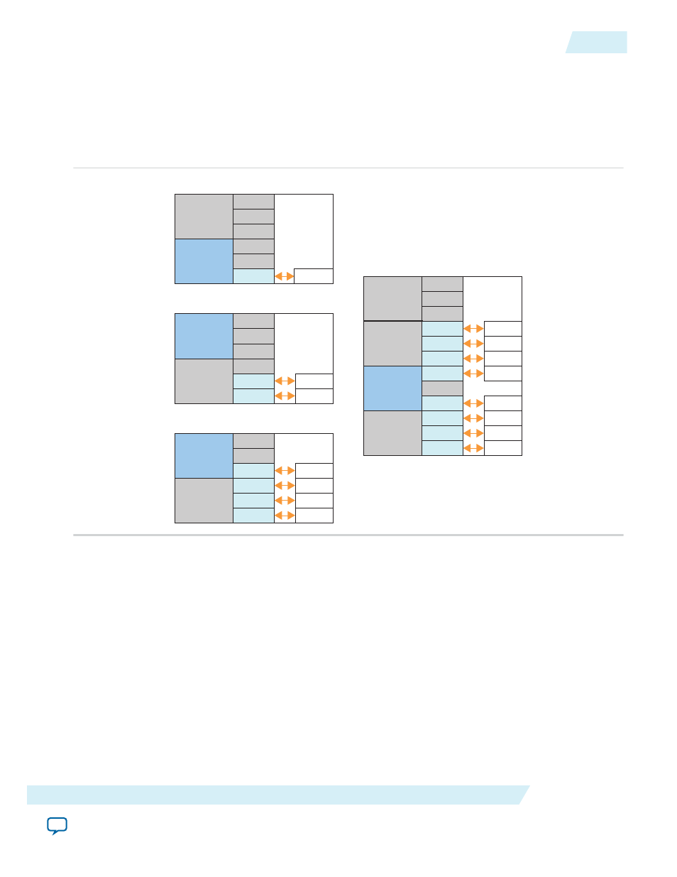
Figure 4-12: Arria V GZ and Stratix V GX/GT/GS Gen1 and Gen2 Channel Placement Using the ATX PLL
Selecting the ATX PLL has the following advantages over selecting the CMU PLL:
• The ATX PLL saves one channel in Gen1 and Gen2 ×1, ×2, and ×4 configurations.
• The ATX PLL has better jitter performance than the CMU PLL.
Note: You must use the soft reset controller when you select the ATX PLL and you cannot use CvP.
ATX PLL0
Ch5
Ch3
Ch2
Ch1
Ch0
ATX PLL0
Ch4
PCIe Hard IP
ATX PLL1
Ch0
Ch5
Ch3
Ch2
Ch1
Ch0
ATX PLL0
Ch4
ATX PLL1
PCIe Hard IP
Ch0
Ch1
Ch5
Ch3
Ch2
Ch1
Ch0
ATX PLL0
ATX PLL0
Ch4
PCIe Hard IP
ATX PLL1
Ch0
Ch1
Ch2
Ch3
Ch5
Ch3
Ch2
Ch1
Ch0
ATX PLL0
ATX PLL1
Ch4
ATX PLL1
Ch0
Ch1
Ch2
Ch3
Ch11
Ch9
Ch8
Ch7
Ch6
Ch10
PCIe Hard IP
Ch5
Ch6
Ch7
Ch4
x1
x8
x2
x4
PIPE Interface Signals
These PIPE signals are available for Gen1, Gen2, and Gen3 variants so that you can simulate using either
the serial or the PIPE interface. Simulation is much faster using the PIPE interface because the PIPE
simulation bypasses the SERDES model . By default, the PIPE interface is 8 bits for Gen1 and Gen2 and 32
bits for Gen3. You can use the PIPE interface for simulation even though your actual design includes a
serial interface to the internal transceivers. However, it is not possible to use the Hard IP PIPE interface in
hardware, including probing these signals using SignalTap
®
II Embedded Logic Analyzer.
Note: The Altera Root Port BFM bypasses Gen3 Phase 2 and Phase 3 Equalization. However, Gen3
variants can perform Phase 2 and Phase 3 equalization if instructed by a third-party BFM.
In the following table, signals that include lane number 0 also exist for lanes 1-7.
UG-01097_avmm
2014.12.15
PIPE Interface Signals
4-31
64- or 128-Bit Avalon-MM Interface to the Application Layer
Altera Corporation