Altera Stratix V Avalon-MM Interface for PCIe Solutions User Manual
Page 61
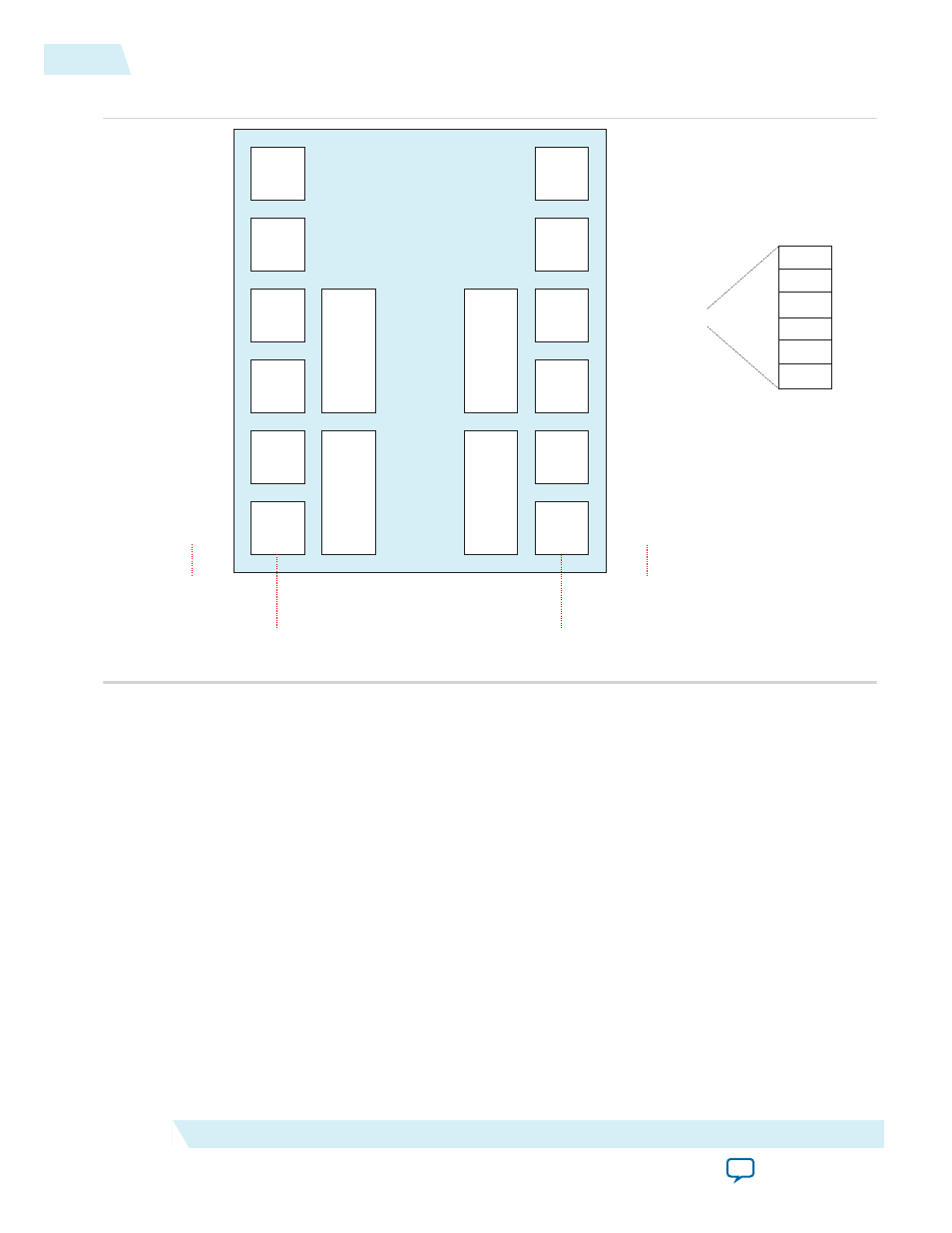
Figure 4-9: Stratix V GX/GT/GS Devices with Four PCIe Hard IP Blocks
3 Ch
6 Ch
6 Ch
6 Ch
6 Ch
6 Ch
3 Ch
6 Ch
6 Ch
6 Ch
6 Ch
6 Ch
PCIe
Hard
IP
PCIe
Hard
IP
PCIe
Hard
IP
IOBANK_B5R
IOBANK_B4R
IOBANK_B3R
IOBANK_B2R
IOBANK_B1R
IOBANK_B0R
IOBANK_B5L
IOBANK_B4L
IOBANK_B3L
IOBANK_B2L
IOBANK_B1L
IOBANK_B0L
Number of Channels
Per Bank
Transceiver
Bank Names
Number of Channels
Per Bank
Transceiver
Bank Names
Ch 5
Ch 4
Ch 3
Ch 2
Ch 1
Ch 0
PCIe
Hard
IP
with
CvP
Smaller devices include the following PCIe Hard IP Cores:
• One Hard IP for PCIe IP core - bottom left IP core with CvP, located at GX banks L0 and L1
• Two Hard IP for PCIe IP cores - bottom left IP core with CvP and bottom right IP Core, located at
banks L0 and L1, and banks R0 and R1
Refer to Stratix V GX/GT Channel and PCIe Hard IP (HIP) Layout for comprehensive information on the
number of Hard IP for PCIe IP cores available in various Stratix V packages.
Related Information
•
•
4-28
Physical Layout of Hard IP in Stratix V GX/GT/GS Devices
UG-01097_avmm
2014.12.15
Altera Corporation
64- or 128-Bit Avalon-MM Interface to the Application Layer