Altera Stratix V Avalon-MM Interface for PCIe Solutions User Manual
Page 49
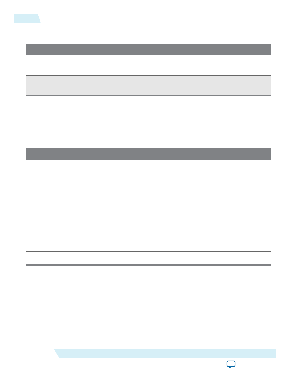
Table 4-8: Transceiver Control Signals
In this table,
Signal Name
Direction
Description
reconfig_from_
xcvr[(
Output
Reconfiguration signals to the Transceiver Reconfiguration
Controller.
reconfig_to_xcvr[(
70)-1:0]
Input
Reconfiguration signals from the Transceiver Reconfiguration
Controller.
The following table shows the number of logical reconfiguration and physical interfaces required for
various configurations. The Quartus II Fitter merges logical interfaces to minimize the number of physical
interfaces configured in the hardware. Typically, one logical interface is required for each channel and one
for each PLL. The ×8 variants require an extra channel for PCS clock routing and control. The ×8 variants
use channel 4 for clocking.
Table 4-9: Number of Logical and Physical Reconfiguration Interfaces
Variant
Logical Interfaces
Gen1 and Gen2 ×1
2
Gen1 and Gen2 ×2
3
Gen1 and Gen2 ×4
5
Gen1 and Gen2 ×8
10
Gen3 ×1
3
Gen3 ×2
4
Gen3 ×4
6
Gen3 ×8
11
For more information about the Transceiver Reconfiguration Controller, refer to the Transceiver Reconfi‐
guration Controller chapter in the Altera Transceiver PHY IP Core User Guide .
Related Information
4-16
Transceiver Reconfiguration
UG-01097_avmm
2014.12.15
Altera Corporation
64- or 128-Bit Avalon-MM Interface to the Application Layer