2 key operation, Standard key operation type, 2 - 2 key operation – Nor-Cal SDC15 Controller User Manual
Page 24
Various displays or settings can be called up on the console through key operation.
Two kinds of general key operation flows are provided, standard key operation type and special key operation type.
A desired key operation type can be selected using the setup setting.
• Standard key operation type: Key operation similar to that of the conventional model SDC10.
• Special key operation type: A part of key operation of the conventional model SDC30 is added to that of the
conventional model SDC10.
The following describes the general flow of each key operation type:
■
Standard key operation type
When the key operation mode/type of the setup setting "C71" is set at "0", the
standard key operation type is selected.
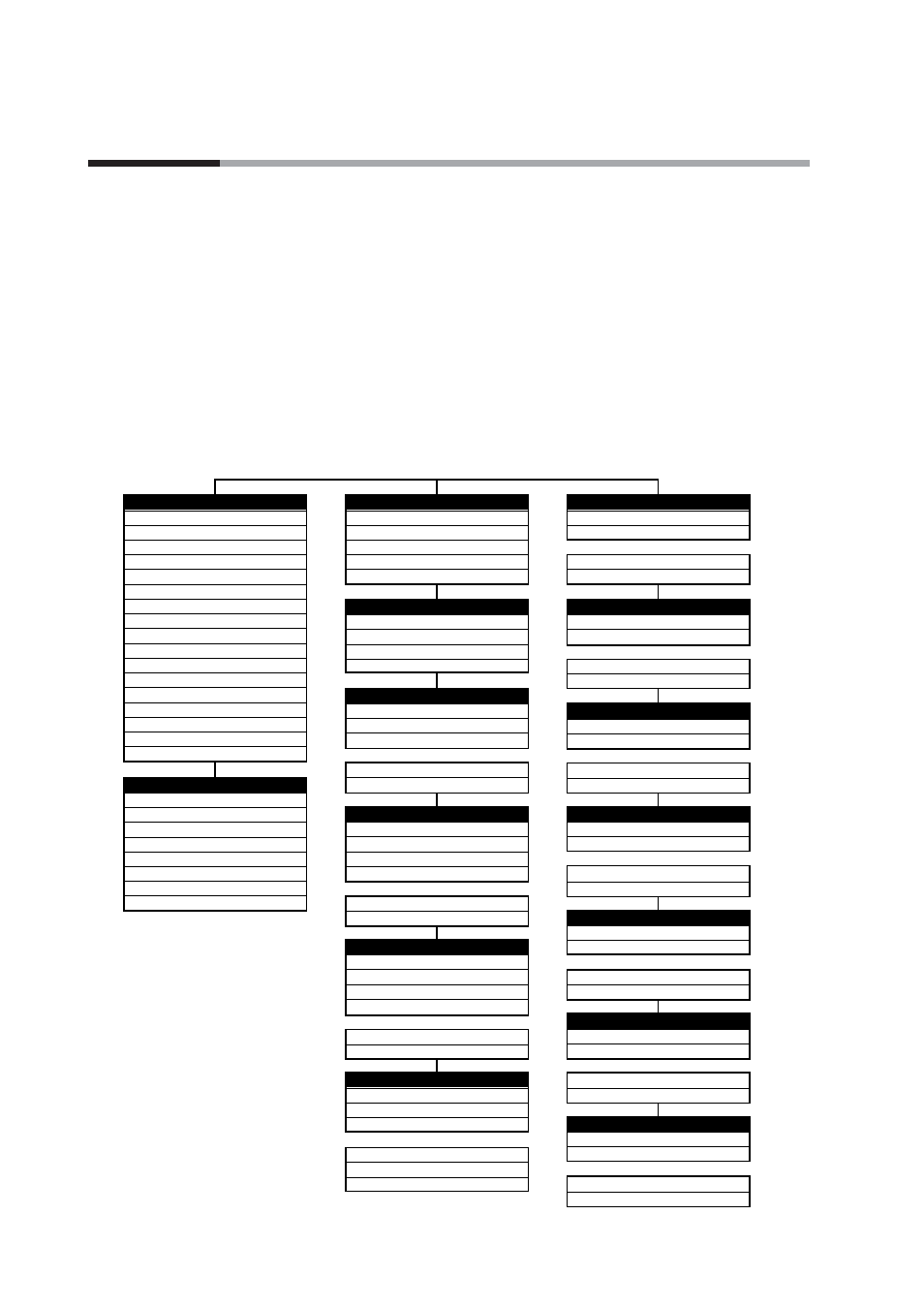
The display and setting data of the standard key operation type are arranged as
shown in the following tree-structure:
Operation display
PV and SP
LSP group selection
MV
Heat MV
Cool MV
AT progress
CT input 1 current value
CT input 2 current value
Internal Event 1 main setting
Internal Event 1 sub setting
Internal Event 1 remain time
Internal Event 2 main setting
Internal Event 2 sub setting
Internal Event 2 remain time
Internal Event 3 main setting
Internal Event 3 sub setting
Internal Event 3 remain time
5-75
5-28
5-76
5-76
5-76
5-76
5-78
5-78
5-48
5-48
5-77
5-48
5-48
5-77
5-48
5-48
5-77
5-79
5-79
5-79
5-79
5-79
5-79
5-79
5-79
User Function (Utilization)
User Function 1
User Function 2
User Function 3
User Function 4
User Function 5
User Function 6
User Function 7
User Function 8
Mode
AUTO/MANUAL
RUN/READY
AT stop/start
Release all DO latches
Communication DI 1
SP
LSP1 group SP
LSP2 group SP
LSP3 group SP
LSP4 group SP
Event
Internal Event 1 main setting
Internal Event 1 sub setting
Internal Event 1 hysteresis
Internal Event 5 ON delay
Internal Event 5 OFF delay
PID
P (Proportional band)
I (Integral time)
D (Derivative time)
Manual reset
Output low limit (Cool)
Output high limit (Cool)
Parameter
Control method
MV low limit at AT
MV high limit at AT
Differential (for ON/OFF control)
SP up ramp
SP down ramp
Extended tuning
AT type
Just-FiTTER settling band
SP lag constant
ST step settling width
ST hunting settling width
ST step ramp change
Setup
PV input range type
Temperature unit
User level
Communication monitor display
Event configuration
Internal Event 1 Configuration 1
Internal Event 1 Configuration 2
Internal Event 5 Configuration 2
Internal Event 5 Configuration 3
DI Assignment
Internal Contact 1 Operation type
Internal Contact 1 Input bit function
Internal Contact 3 Polarity
Internal Contact 3 Internal Event channel def.
DO Assignment
Control Output 1 Operation type
Control Output 1 Output Assign A
Event output 3 Polarity
Event output 3 Latch
User Function
User Function 1
User Function 2
User Function 7
User Function 8
Lock
Key lock
Communication lock
Password 1B
Password 2B
Instrument information
ROM ID
ROM version 1
Manufacturing date code (month, day)
Serial No.
•••
••
•
••
•
••
•
••
•
••
•
•••
••
•
••
•
•••
(Note) The figures shown on the right of the display and setting columns in the tree-structure indicate the relevant pages.
2 - 2 Key Operation
2-2
Chapter 2. OUTLINE OF FUNCTIONS