Mode display setup – Nor-Cal SDC15 Controller User Manual
Page 124
5-74
Chapter 5. DETAILED DESCRIPTION OF EACH FUNCTION
■
MODE display setup
Whether or not the mode related setup items of the parameter setting and mode
bank are displayed can be set.
• When using the Smart Loader Package
SLP-C35
, not only the numeric value,
but also the bit input can be used to set [MODE display setup: C73].
Handling Precautions
• Even though the AUTO/MANUAL display is set at [Displayed], the
AUTO/MANUAL is not displayed when [CtrL: Control method] is set at
“0” (ON/OFF control).
• Even though the AT stop/start display is set at [Displayed], the AT
stop/start is not displayed when [CtrL: Control method] is set at “0”
(ON/OFF control).
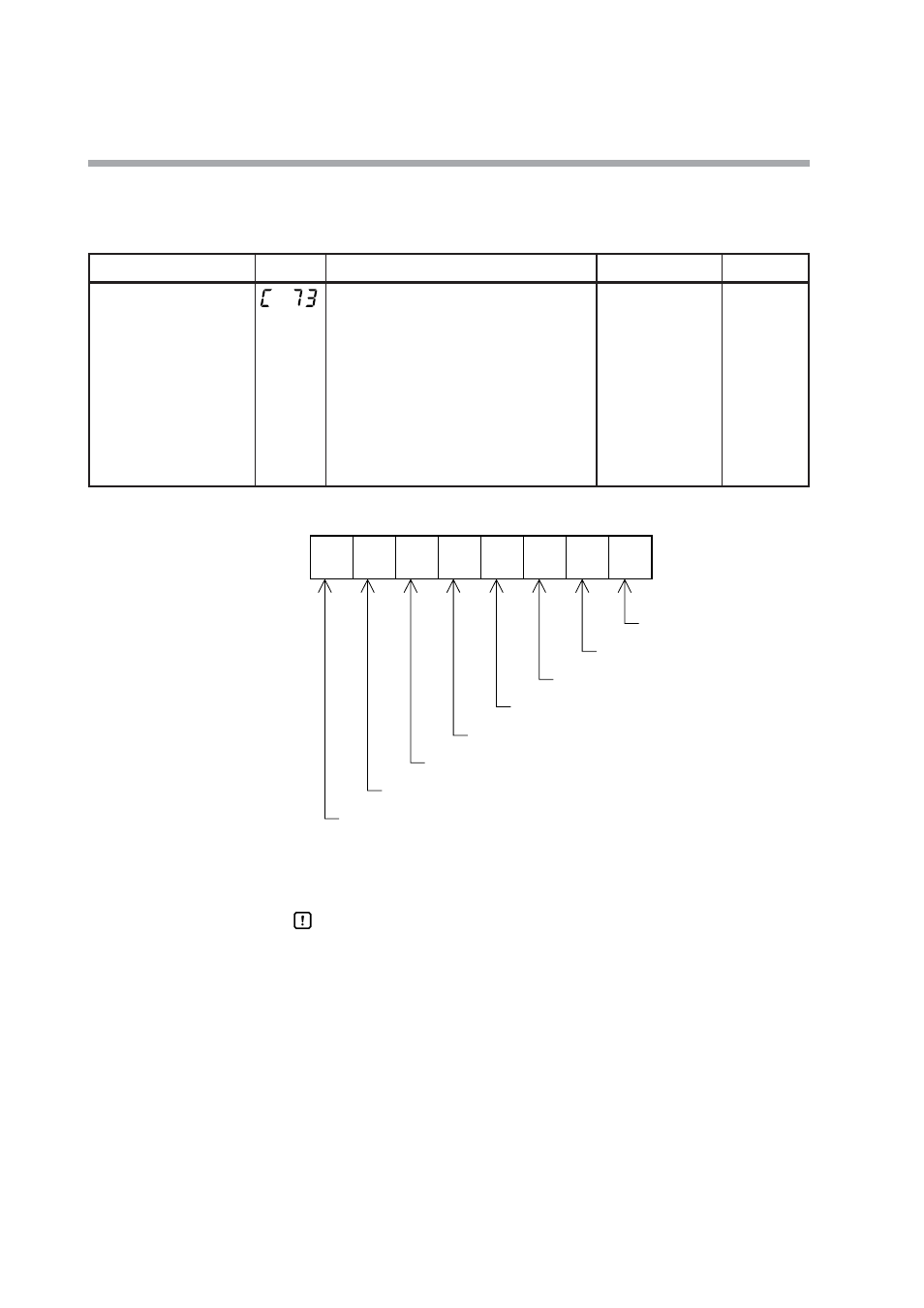
Item (Setting display/bank)
Display
Contents
Initial value
User level
MODE display setup
(Setup setting/Setup bank)
Whether or not the mode bank setup is
displayed is determined by the sum of the
following weights:
Bit 0: AUTO/MANUAL display
Disabled: 0, Enabled: +1
Bit 1: RUN/READY display
Disabled: 0, Enabled: +2
Bit 3: AT stop/start display
Disabled: 0, Enabled: +8
Bit 4: Release all DO latches display
Disabled: 0, Enabled: +16
Bit 5: Communication DI1 ON/OFF display
Disabled: 0, Enabled: +32
Other invalid settings, 0, +4, +64, +128
255
Standard,
High function
2
7
2
6
2
5
2
4
2
3
2
2
2
1
2
0
Undefined.
Undefined.
Communication DI1 ON/OFF display
Release all DO latches display
AT stop/start display
Undefined.
RUN/READY display
AUTO/MANUAL display