Parameter bank, Bank selection – Nor-Cal SDC15 Controller User Manual
Page 140
6-6
Chapter 6. LIST OF DISPLAYS AND SETTING DATA
■
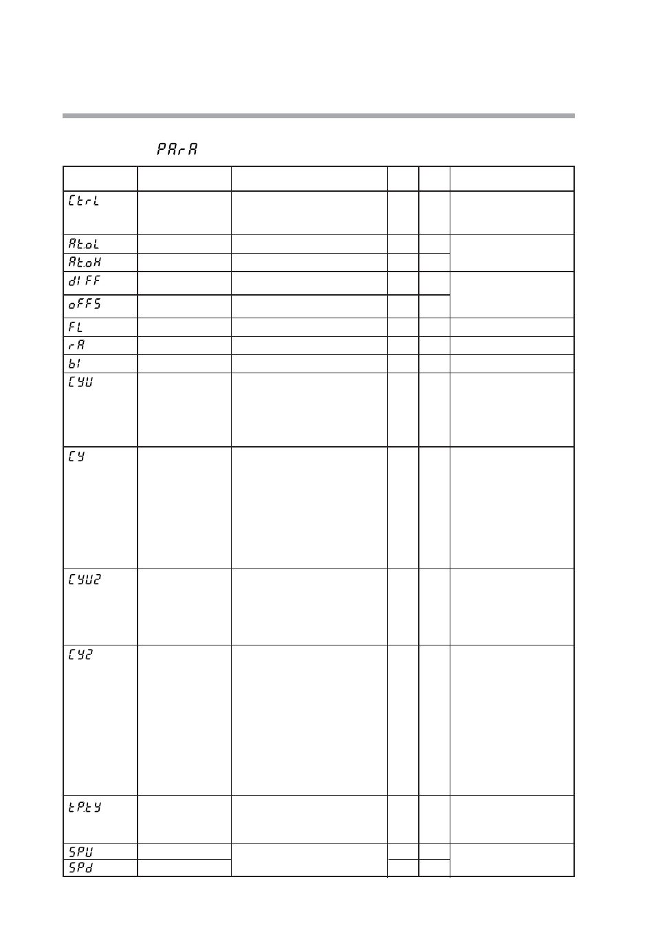
Parameter bank
Bank selection:
Display
Item
Contents
Initial
value
User
level
Remarks
Control method
0: ON/OFF control
1: Fixed PID
2: ST (Self-tuning)
0
or
1
0
The initial value is “0” when
control output 1 is relay
output. The initial value is “1”
in other cases.
MV low limit at AT
-10.0 to +110.0%
0.0
0
Displayed when the control
method is other than the
ON/OFF control (CtrL
≠
0).
MV high limit at AT
-10.0 to +110.0%
100.0
0
Differential
(for ON/OFF control)
0 to 9999U
5
0
Displayed when the control
method is other than the
ON/OFF control (CtrL
≠
0).
ON/OFF control
action point offset
-1999 to +9999U
0
2
PV filter
0 to 120.0s
0.0
0
PV ratio
0.001 to 9.999
1.000
1
PV bias
-1999 to +9999U
0
0
Time proportional
cycle unit 1
0: Unit of “1s”
1: Fixed at “0.5s”.
(Cycle time setting is disabled.)
2: Fixed at “0.2s”.
(Cycle time setting is disabled.)
3: Fixed at “0.1s”.
(Cycle time setting is disabled.)
0
2
Displayed when MV1 (time
proportional output (heat) of
Heat/Cool control) is
connected to the relay
control output, voltage pulse
output, or event output in the
DO Assignment.
The initial value of Time
proportional cycle 1 is “10”
when the control output is the
relay output. The initial value
is “2” in other cases.
Time proportional
cycle 1
5 to 120s (Output includes the relay
output.)
1 to 120s (Output does not include
the relay output.)
10
or
2
0
Time proportional
cycle unit 2
0: Unit of “1s”
1: Fixed at “0.5s”
(Cycle time setting is disabled.)
2: Fixed at “0.2s”.
(Cycle time setting is disabled.)
3: Fixed at “0.1s”.
(Cycle time setting is disabled.)
0
2
Displayed when the
Heat/Cool control is used
(C26=1) and MV2 (time
proportional output (heat) of
Heat/Cool control) is
connected to the relay
control output, voltage pulse
control output, or event
output.
The initial value of Time
proportional cycle 2 is “10”
when the model has one
control output point. The
initial value is “2” in other
cases.
Time proportional
cycle 2
5 to 120s (Output includes the relay
output.)
1 to 120s (Output does not include
the relay output.)
10
or
2
0
Time proportional
cycle mode
0: Controllability aiming type
1: Operation end service life aiming
type (Only one ON/OFF operation
within Time proportional cycle)
0
or
1
2
The initial value is “1” when
control output 1 is the relay
output. The initial value is “0”
in other cases.
SP up ramp
0.0 to 999.9U
(No ramp when set at “0.0U”)
0.0
2
Time unit of the ramp is
selected by the SP ramp unit
(C32).
SP down ramp
0.0
2
Displayed under the same
conditions as
CY
except that a
relay is not included in the
output.
Displayed under the same
conditions as
CY2
except that
a relay is not included in the
output.