Chapter 10. maintenance and troubleshooting, Maintenance, Alarm displays and corrective action – Nor-Cal SDC15 Controller User Manual
Page 199
Chapter 10. MAINTENANCE AND
TROUBLESHOOTING
10-1
■
Maintenance
●
Cleaning
When removing the dirt from the measuring instrument, wipe it off with a soft
cloth rag. At this time, do not use any organic solvent, such as paint thinner or
benzene.
●
Part replacement
Do not replace any parts of this unit.
●
Fuse replacement
When replacing the fuse connected to the electric wiring, always use the specified
standard fuse.
Standard
IEC127
Shut-down speed
Slow-action type (T)
Rated voltage
250V
Rated current
200mA
■
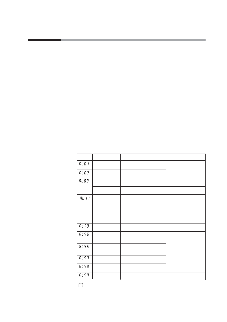
Alarm displays and corrective action
The following Table shows the alarm displays and corrective actions if any failure
occurs in this unit:
Alarm code
Failure name
Cause
Corrective action
PV input failure
Sensor burnout, incorrect wiring,
(Over-range)
incorrect PV input type setting
PV input failure
Sensor burnout, incorrect wiring,
(Under-range)
incorrect PV input type setting
CJ failure
Terminal temperature is faulty
(thermocouple).
PV input failure
Sensor burnout, incorrect wiring Check the wiring.
(RTD)
CT input failure
A current exceeding the upper
(over-range)
limit of the display range was
(CT input 1 or 2,
measured. The number of CT
or both)
turns or the number of CT
power wire loops is incorrectly
set, or wiring is incorrect.
A/D conversion
A/D converter is faulty.
failure
Parameter failure
Data is corrupted by noise, or
power is shut-down while the
data is being set.
Adjustment data
Data is corrupted by noise, or
failure
power is shut-down while the
data is being set.
Parameter failure
Data is corrupted by noise.
(RAM area)
Adjustment data
Data is corrupted by noise.
failure (RAM area)
ROM failure
ROM (memory) is faulty.
Check the wiring.
Set the PV input type
again.
Check the ambient
temperature.
Replace the unit.
• Restart the unit.
• Set the data again (set
data for AL95/97 and
adjustment data for
AL96/98).
• Replace the unit.
• Restart the unit.
• Replace the unit.
• Use a CT with the correct
number of turns for the
display range.
• Reset the number of CT
turns.
• Reset the number of CT
power wire loops.
• Check the wiring.
Handling Precautions
• If ROM version 1 of the instrument information bank (
Id02
) is prior to
2.04, CT input failure (AL11) is not displayed.