2 message structure, Message structure, 8 - 2 message structure – Nor-Cal SDC15 Controller User Manual
Page 177
8 - 2
Message Structure
■ Message structure
This section describes the message structure.
All messages are expressed in hexadecimal.
● MODBUS ASCII
All messages other than delimiters are written in hexadecimal ASCII codes.
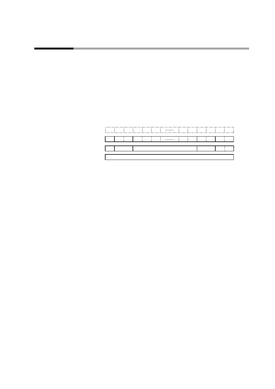
A message of MODBUS ASCII consists of (1) to (6) below.
The application layer stores commands, which are transmission contents from the
master station and responses, which are transmission contents from the slave
station.
All messages use ASCII codes (Each slot below corresponds to one character.)
(1) Start of message (colon, expressed with ASCII code 3AH)
(2) Station address (2 bytes)
(3) Send message, response message
(4) Checksum (two-byte LRC)
(5) CR (delimiter)
(6) LF (delimiter)
• Colon (3AH)
When a colon (3AH) is received, the device judges this to be the start of the send
message. For this reason, the device returns to the initial state whatever
reception state it was in, and processing is started on the assumption that the
colon (3AH), the first character, has been received. The purpose of this is to
enable recovery of the device's response at the next correct message (e.g.
RETRY message) from the master station in the event that noise, for example,
causes an error in the sent message.
• Station address
Of the messages sent by the master station, the device creates response messages
only when station addresses are the same. Station addresses in messages are
expressed as two hexadecimal characters. The station address is set up by the
station address setup (setup setting C65). However, when the station address is
set to 0 (30H 30H), the device creates no response even if station addresses
match. The device returns the same station address as that received as the
response message.
• Checksum (LRC)
This value is for checking whether or not some abnormality (e.g. noise) causes
the message content to change during communications. The checksum is
expressed as two hexadecimal characters. The method to calculate a checksum is
as follows:
(1) Add the data from the top up to just before the checksum. Note that the
values to be added are not the ASCII character values in the send message but
8-3
Chapter 8. MODBUS COMMUNICATIONS FUNCTIONS
(4)
(5)
3AH
0DH
:
0AH
CR LF
(2)
(1)
(3)
(6)
1 frame