Nor-Cal SDC15 Controller User Manual
Page 112
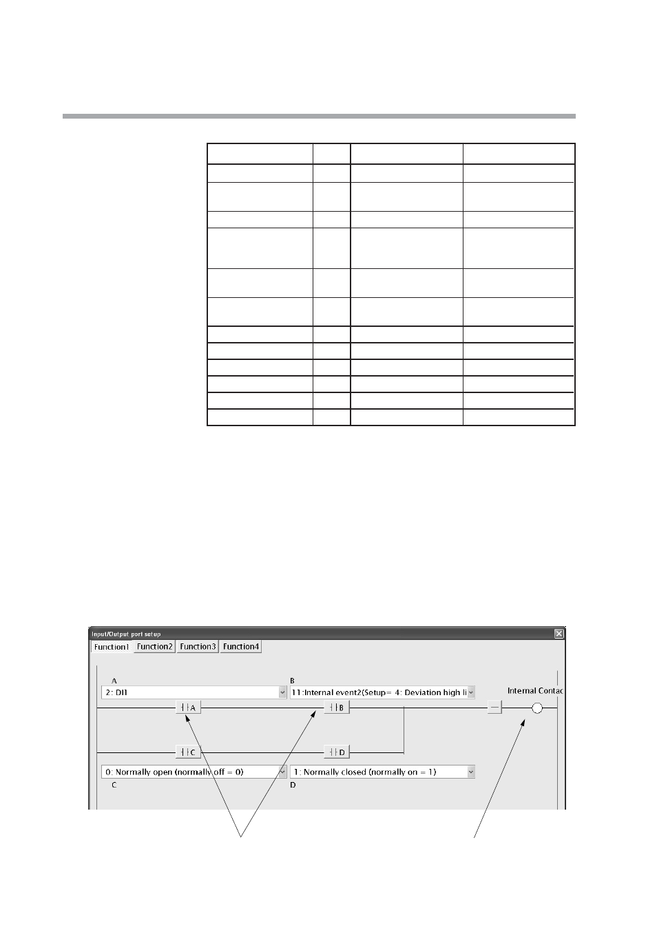
• DI Assignment
Note. The internal DI No. is indicated at the mark of "x" shown in the Display
column.
◆
Setting points
The timer startup conditions are set to logical AND of DI1 and temperature
attainment (Internal Event 2: Deviation high limit).
The mode (RUN/READY) selection is used as conditions for logical AND of the
A contact of DI1 and the B contact of the timer. However, since the mode is the
READY mode when the contact is ON, it is reversed in the final stage of internal
contact 2.
DI Assignment (Internal Contact 1): Input/Output port setup
5-62
Chapter 5. DETAILED DESCRIPTION OF EACH FUNCTION
DI Assignment
Display
Internal Contact 1
Internal Contact 2
Operation type
DIx.1
17: Timer stop/start
7: RUN/READY
Input bit function
DIx.2
1: Function 1 (A and B) or
1: Function 1 (A and B) or
(C and D)
(C and D)
Input assign A
DIx.3
2: DI1
2: DI1
Input assign B
DIx.4
11: Internal Event 2
10: Internal Event 1
(Setting = 4: Deviation
(Setting = 32: Timer
high limit)
(Status))
Input assign C
DIx.5
0: Normally opened.
0: Normally opened.
(Normally Off = 0)
(Normally Off = 0)
Input assign D
DIx.6
0: Normally opened.
0: Normally opened.
(Normally Off = 0)
(Normally Off = 0)
Polarity A
DIx.7
0: Direct
0: Direct
Polarity B
DIx.7
0: Direct
1: Reverse
Polarity C
DIx.7
0: Direct
0: Direct
Polarity D
DIx.7
0: Direct
0: Direct
Polarity
DIx.8
0: Direct
1: Reverse
Event channel def.
DIx.9
1
----
Logical AND of DI1 and deviation high limit event
Timer start-up contact