User function bank, Lock bank, Bank selection – Nor-Cal SDC15 Controller User Manual
Page 157
6-23
Chapter 6. LIST OF DISPLAYS AND SETTING DATA
■
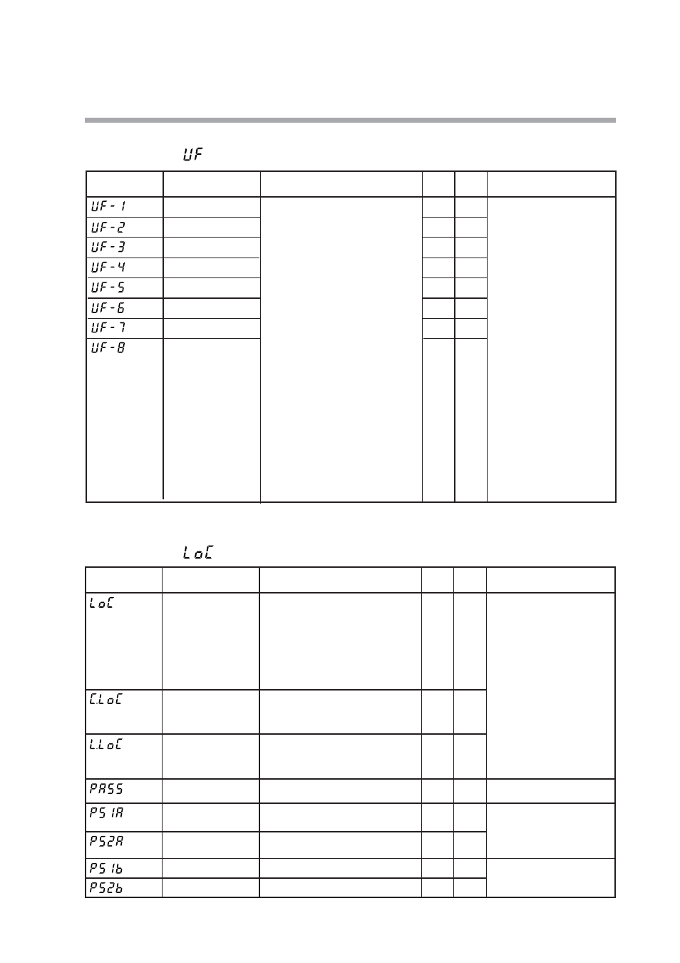
User Function bank
Bank selection:
■
Lock bank
Bank selection:
Display
Item
Contents
Initial
value
User
level
Remarks
User Function 1
Each setting is set on the upper display.
The following shows the setting
exceptions:
----
: Not registered.
P--
: Proportional band of currently
used PID group
I--
: Integral time of currently used
PID group
d--
: Derivative time of currently
used PID group
rE--
: Manual reset of currently
used PID group
OL--
: Output low limit of currently
used PID group
OH--
: Output high limit of currently
used PID group
P--C
: Proportional band for cool
side of currently used PID
group
I--C
: Integration time for cool side
of currently used PID group
d--C
: Derivative time for cool side
of currently used PID group
OL.-C
: Output low limit for cool side
of currently used PID group
OH.-C
: Output high limit for cool side
of currently used PID group
----
1
User Function 7
----
1
User Function 2
----
1
User Function 3
----
1
User Function 4
----
1
User Function 5
----
1
User Function 6
----
1
It is possible to register only
the settings, which can be
displayed.
(Example: Manual reset of
the PID constant can be
registered when the I
(Integral time) is set at “0”.)
The registered setting is
added to the end of the
display order of the basic
display.
User Function 8
----
1
Display
Item
Contents
Initial
value
User
level
Remarks
Key lock
0: All settings are possible.
1: Mode, event, operation display,
SP, UF, lock, manual MV, and
mode key can be set.
2: Operation display, SP, UF, lock,
manual MV, and mode key can be
set.
3: UF, lock, manual MV, and mode
key can be set.
0
0
Password 1A
0000 to FFFF (Hexadecimal value)
0000
0
Communication lock
0
2
Loader lock
0: Loader communication read/write
enabled.
1: Loader communication read/write
disabled.
0
2
Password display
0 to 15
5: Password 1A to 2B display
0
0
When two sets of passwords
(1A and 1B, 2A and 2B) are
matched, the setting is
possible.
[mode] key operation, MV
setting in MANUAL mode,
key lock, password display,
and password 1A to 2B can
be set when the key lock
(LoC) is a value of 0 to 3.
Displayed when the
password display (PASS) is
“5” and two sets of
passwords (1A and 1B, 2A
and 2B) are matched.
0: RS-485 communication read/write
enabled.
1: RS-485 communication read/write
disabled.
Password 2A
0000 to FFFF (Hexadecimal value)
0000
0
Password 1B
0000 to FFFF (Hexadecimal value)
0000
0
Displayed when the
password display (PASS) is
“5”.
Password 2B
0000 to FFFF (Hexadecimal value)
0000
0