Nor-Cal SDC15 Controller User Manual
Page 121
5-71
■
Number of CT turns and number of CT power wire loops
Each CT of CT inputs 1 and 2 can be set.
• If the controller has two CT inputs, this item is displayed and can be set.
• For the number of turns, use the number of CT turns divided by 100. For
example, if the number of CT turns is 400, set at 4. (However, a setting of 0 has
the same meaning as 8, namely 800 CT turns.) If using the optional QN206A or
QN212A, which have 800 turns, set at 8.
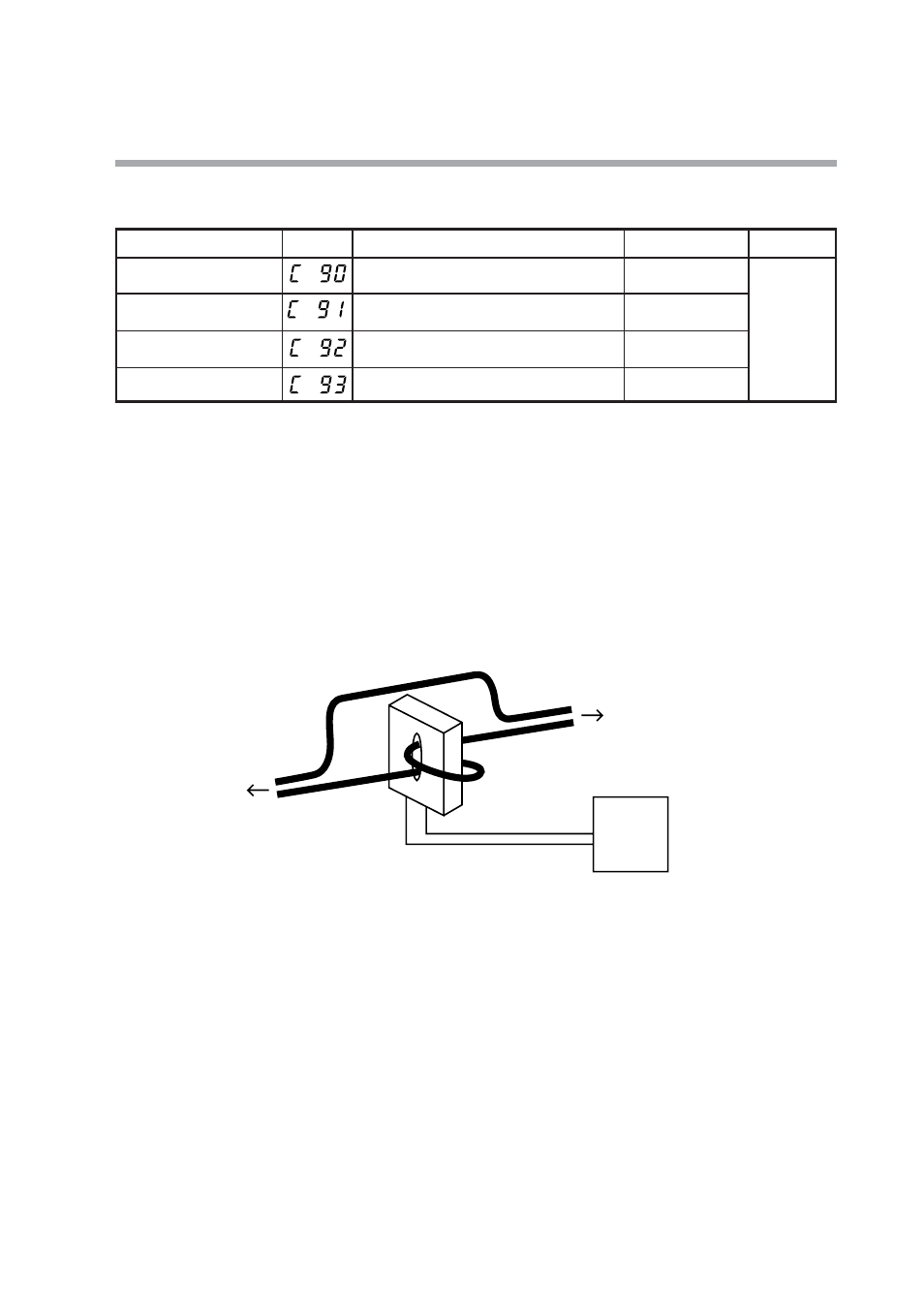
• For the number of power wire loops, use the number of times the power wire
passes through the CT hole. For example, if the power wire passes through the
CT hole 2 times, set at 2. (However, a setting of 0 has the same meaning as 1,
namely that there is 1 power wire loop).
Chapter 5. DETAILED DESCRIPTION OF EACH FUNCTION
Item (Bank)
Display
Contents
Initial value
User level
Number of CT1 turns
(Setup bank)
0: 800 turns
1 to 40: CT turns devided by 100
8
High function
Number of CT1 power wire
loops(Setup bank)
1
Number of CT2 turns
(Setup bank)
0: 800 turns
1 to 40: CT turns devided by 100
8
Number of CT2 power wire
loops(Setup bank)
1
0: 1 times
1 to 6: Number of times
0: 1 time
1 to 6: Number of times
Heater etc.
Power wire
CT
CT input
This device
Relay and power supply etc.