0 mounting (cont’d), 3 curb cap base and mounting (cont’d), Roof curb – Reznor ZQYRA Unit Installation Manual User Manual
Page 8: 2 mounting on a roof curb (cont’d)
Form I-ZQYRA P/N 260414R5, Page 8
5.0 Mounting
(cont’d)
5.3 Curb Cap Base
and Mounting
(cont’d)
5.3.2 Mounting on a
Roof Curb (cont’d)
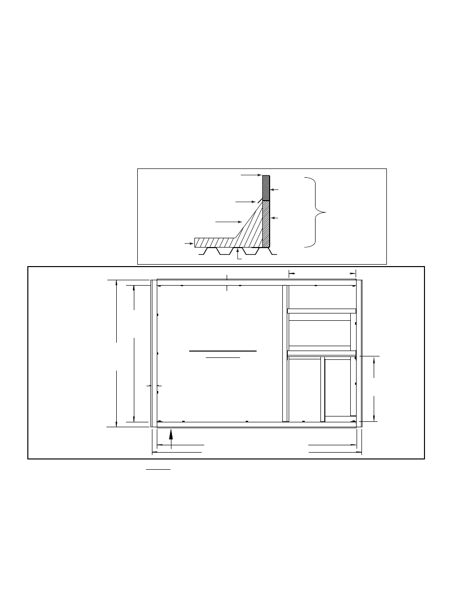
Roofing Felts
(by others)
Cant Strip
(by installer)
Counter Flashing
(by installer)
MUST be sealed between
curb cap and roof curb.
2 x 6
Wood
Nailer
Insulation
Weld, bolt, or lag screw curb to deck structure.
Roof Curb
FIGURE 7 - Cross-
section of Roof Curb
showing Construction
Detail
7.
Before lifting and placing the unit on the curb, check the following:
□
The curb is designed for ductwork to be installed from the top BEFORE the unit
is in place. Slide the ductwork down into the discharge and return air openings.
See dimensions in
FIGURE 8. Ductwork should be sized slightly smaller with a
minimum 3/4" duct flange that will attach to all sides of the duct connection in the
curb. See Paragraph 6.2 for connecting ductwork.
□
Apply 1/4" x 1-1/4" foam sealant tape to both the top surface of the curb rails and
the top surface of the duct connection supports, being sure to make good butt
joints at all corners. The sealant tape must be applied to the rails to prevent water
leakage into the curb area due to blown rain and capillary action.
□
The unit has field convertible (either vertical or horizontal) supply and return air
opening locations. Depending on whether the ductwork is vertical or horizontal,
44-1/8”
(1121mm)
- inside
of curb
47-7/16”
(1205mm)
- outside
of rails
Rail Width
1-21/32”
(42mm)
Rail Width
1-21/32”
(42mm)
Outside Air Inlet Location
(on side of unit)
TOP VIEW of Assembled
ROOF CURB
Exhaust Air
Outlet Location
(on side of unit)
Supply Air
Opening
18-7/32” x 8-1
1/64”
(463mm x 2
08mm)
64-5/32” (1629mm) - inside of curb
67-15/32” (1713mm) - outside of rails
21-1/2”
(546mm)
Return Air Opening
19-51/64” x 8-11/64”
(503mm x 208mm)
22-1/4” (565mm)
Horizontal Return
Air Opening
Location on
Side of Unit
Supply
Air Opening
Location on
Side of Unit
FIGURE 8 -
Option CJ3C
Roof Curb and
Duct Opening
Dimensions
Slide return
air and supply
ductwork down
from the top
and attach to
duct flanges.
Apply sealant
tape to top of all
curb rails.
Instructions and Requirements for Assembling and Installing Roof Curb
Option CJ3C (cont’d)
3. Identify the duct supports that create the integral supply and return air ductwork.
NOTE: If the system is not using the vertical duct openings, the duct support parts
are not required but may be installed.
Position the duct support parts as shown in
FIGURE 6 and attach. Use 1-1/4” lag
screws with lockwashers when attaching supports to the top portion of the curb
rails with the wood nailer. Use sheetmetal screws in all other locations.
4. Check the roof curb for squareness. The curb must be adjusted so that the
diagonal measurements are equal within a tolerance of ±1/8" (3mm).
5. Level the roof curb. To ensure a good weatherproof seal between the cabinet curb
cap and the roof curb, the curb must be leveled in both directions with no twist end
to end. Shim as required and secure curb to the roof deck before installing flashing
(See Curb Detail in
FIGURE 7).
6. Install field-supplied flashing.