Roof curb, option cj3c – Reznor ZQYRA Unit Installation Manual User Manual
Page 7
Form I-ZQYRA P/N 260414R5, Page 7
Roof Curb,
Option CJ3C
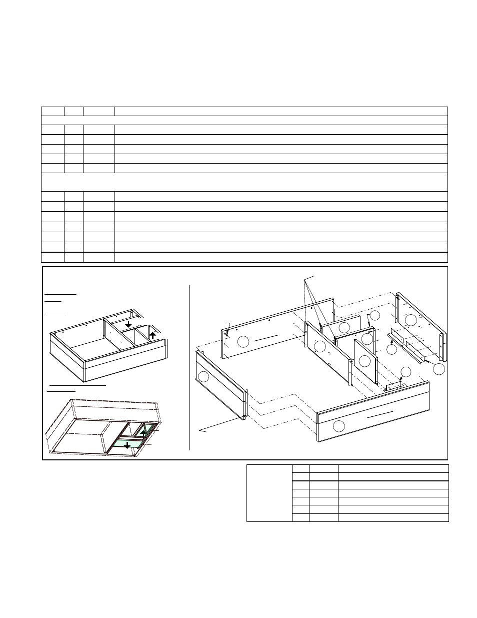
Roof curb Option CJ3C, is shipped separately for field installation. The roof curb
designed for this system includes integral duct connections for supply air and return air
making it very important to know the orientation of the unit when installing the
curb. See the illustrations in FIGURE 6 and the component list below. See dimensions
in
FIGURE 8, page 8 and orientation in FIGURE 9, page 9.
The roof curb is designed for ductwork to be installed from the top prior to setting the
unit. If ductwork is installed after the unit, field-fabricated custom connections will be
required as the unit does not have duct flanges.
FIGURE 6 - Layout of Roof Curb Components listed above
Item Qty
P/N
Description
Roof Curb Rail and Cross Support Parts, Items A, B, C, D, and E are ALWAYS used:
A
1
260215 Roof Curb Front Side
B
1
260216 Roof Curb Right End
C
1
260217 Roof Curb Left End
D
1
260218 Roof Curb Rear Side
E
1
259636 Roof Curb Center Support
Vertical Duct Support Parts (Items F-M) are required if the application has vertical supply and return air.
Installation of these parts is optional if installing a unit using the horizontal supply and return air openings.
F
1
259637 Roof Curb Cross Support (return air)
G
1
259638 Roof Curb Cross Support (discharge air)
H
1
259639 Roof Curb Cross Support (return air)
J
1
259640 Roof Curb Center Support (discharge air)
K
1
259641 Duct Angle Support (discharge air right end)
L
1
259642 Duct Angle Support (discharge air front side)
M
1
259643 Duct Angle Support (return air right end)
1
2
3
4
5
6
7
8
9
10
11
(Right End)
(Center
Support)
(Left End)
Top View (showing supply
and return airflow)
(Front Side)
(Rear Side)
L
A
J
E
G
C
F
M
B
D
H
K
Use 3/4” Cap Screw, P/N 16247,
with Lockwasher, P/N 1333, and Nut,
P/N 1035, in bottom two holes in each corner.
Use 1-1/4” Lag Screw, P/N 16243,
with Lockwasher, P/N 1333, in all
attachmentsmade into the wood
nailer around the top
of the curb.
Use sheetmetal screws, P/N 11813, for
attaching duct support parts to each
other and to the insulated portion of
the curb rails.
Assembled
Views
Slide vertical ductwork down from the top
and attach to duct flanges at bottom of curb.
See dimensions on page 8.
Bottom View (from inside the building showing flanges for
ductwork on the openings on the bottom of the curb)
Return Air
Duct Flange
Supply Air
Duct Flange
Return Air
Supply Air
Components in Option
CJ3C, Pkg P/N 260418
Instructions and
Requirements for
Assembling and
Installing Roof Curb
Option CJ3C
The option package
includes the following
hardware:
Roof Curb
Hardware
Bag
includes:
Qty
P/N
Description
10 16243 Hex Hd Lag Bolt 5/16 X 1-1/4” lg
18
1333 Lockwasher 5/16 In.
8
16247 Cap Screw 5/16 X 3/4” lg
8
1035 Hex Nuts
31
11813 S/M Screw #10-16x1/2 Ab Stalgd
66302 Roll of Sealant Tape, 1/4” x 1-1/4”
1. Verify that the roof curb parts match those listed in the package component table
and the hardware bag component table above.
Verify that the location has adequate support for the weight (Paragraph 5.1).
2. Position the roof curb end and side assemblies as shown in
FIGURE 6. Fasten
each corner using lag screws with lockwashers in the top holes and cap screws
with lockwashers and nuts in each of the other holes. Install the center support.
Before continuing to Step 3, verify that the airflow orientation is correct.