0 dimensions and clearances, 0 receiving, moving, and uncrating (cont’d), 1 dimensions – Reznor ZQYRA Unit Installation Manual User Manual
Page 4: 3 uncrating and preparation, 2 storage and moving (cont’d), Figure 1 - dimensions - inches (mm)
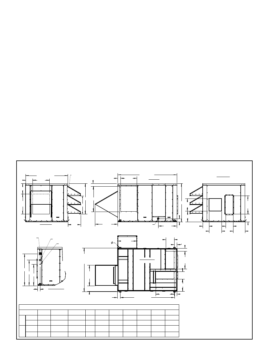
Form I-ZQYRA P/N 260414R5, Page 4
4.0 Dimensions and Clearances
4.1 Dimensions
Dimensions - inches and mm
Size
A
B
C
D
E
F
G
H
J
K
8
inches
9-1/4 14-5/16 32-15/16 24 39-1/2 9-3/4 6-1/4 34-7/8 27-3/8 22-3/8
mm
235
364
837
610 1003
248
159
886
695
568
12
inches
12-1/4 21-3/8 36-5/16 30 45-1/2 12-3/4 9-1/4 37-7/8 30-3/8 25-3/8
mm
311
543
922
762 1156
324
235
962
772
645
FIGURE 1 - Dimensions - inches (mm)
3.3 Uncrating and
Preparation
Immediately upon uncrating, check the electrical characteristics to verify that the unit
is suitable for the installation site.
Shipped-with and Shipped-separate Items - A carton shipped inside the unit con-
tains the vertical supply air opening cover and parts to assemble and install the inlet
and exhaust hoods. The hoods will be attached after the unit is in the installed loca-
tion.
Before beginning installation, be sure that all shipped-separate options ordered are
available at the site. Shipped-separate options could include a roof curb, a wall-
mounted control, and/or a disconnect switch.
Supply Air (Discharge) and Return Air Openings - To enable the installer to adapt
to either vertical or horizontal ductwork, the cabinet has both vertical and horizontal
supply and return air openings. Both the horizontal supply air and return air openings
are capped during shipping.
NOTE: There are no vertical duct connections on the unit; duct flange connections are
part of the roof curb. The curb is designed to slide the ductwork into the vertical duct
openings from the roof before the unit is lifted to the curb.
* Configuration of
Supply (Discharge)
Air and Return Air
Ductwork can be either
Vertical or Horizontal
Follow the instructions in
Paragraph 6.2 that apply.
NOTE: Vertical duct
connections are on the roof
curb. There are no vertical
duct flanges on the unit.
The curb is designed for
ductwork to be installed
from the top before the unit
is set on the curb.
A
24
(610)
Exhaust
Air
Opening
15-3/8
(391)
Inlet Air
Filter
Access
Panel
REAR VIEW
(Exhaust End)
3-3/8
(86)
3-3/8
(86)
19-1/2
(495)
Inlet Air
Opening
Exhaust
Hood
B
27 (686)
Wheel
Access
Panel
Supp
ly
Fan Access Panel
Inlet
Side
Post
Cover
3/4” SCH 40
Condensate Drain
Socket Adapter Fitting
22-1/8
(562)
3-7/8
(98)
70-1/2 (1791)
C
D
E
*Horizontal
(Discharge)
Supply Air
Opening
*Horizontal Return Air
22
(559)
9
(229)
14-1/4
(362)
15 (381)
7-9/16
(141)
15
(381)
F
G
Electrical
Compartment
- Controls
and
Compressors
Return Air
Filter
Access Panel
H
K
J
Non-fused
Optional
Disconnect
Switch
High Voltage Entrance
Low Voltage Entrance
3
(76)
52-11/32
(1330)
(lifting hole
centerline)
64-1/2 (1638)
(lifting lug centerline)
Exhaust
Hood
24-1/2
(622)
6-1/2 (165)
Inlet Hood
22-15/16
(583)
10
(254)
22 (559)
14-3/8 (365)
*Vertical Return
Air Opening
*Optional Supp
ly Air
Opening
9 (229)
21
(533)
3-3/8 (86)
3-5/16 (84)
1-1/2 (38)
4 Lifting Holes
CONTROL SIDE
(Partial view)
8-1/2
(216)
20
(508)
50-3/8 (1280)
Inlet Air Hoods
Size 8 - 2 Hoods
Size 12 - 3 Hoods
BOTTOM VIEW
(from underneath)
3-5/16
(84)
SIDE VIEW
(Side Opposite Controls)
FRONT VIEW
(Horizontal Supply and
Return Air Connections)
(Reheat
Pump
Coil)
If the unit is going to be stored, take precautions to prevent condensation inside the
electrical compartment and motors. To prevent damage to the unit, do not store sitting
on the ground.
3.0 Receiving,
Moving, and
Uncrating
(cont’d)
3.2 Storage and Moving (cont’d)