Model zqyra startup form, Appendix (cont’d), Startup form – Reznor ZQYRA Unit Installation Manual User Manual
Page 71
Form I-ZQYRA P/N 260414R5, Page 71
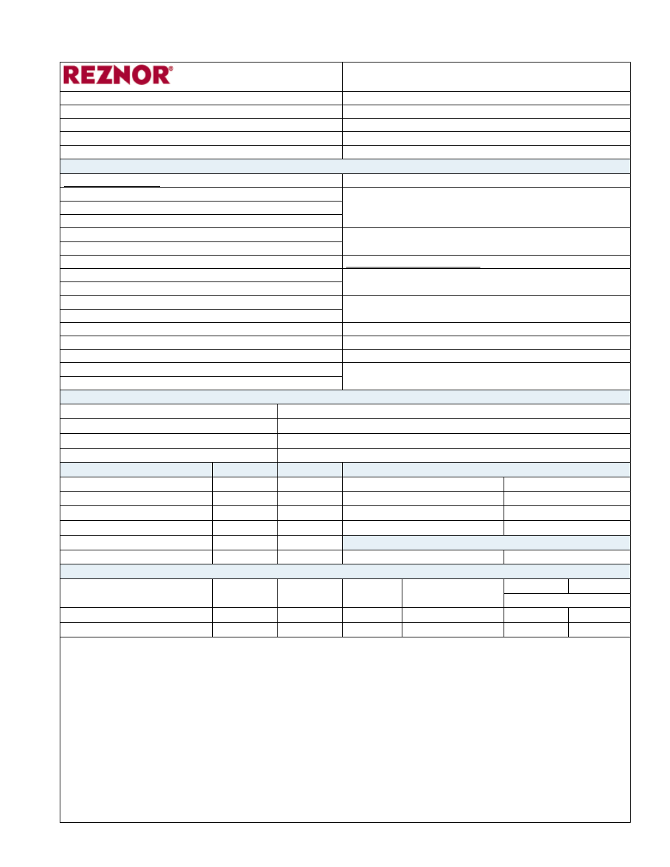
Startup Form
Model ZQYRA Startup Form
Job Name:
Contractor Contact:
Street Address
Contractor Phone:
City, State, Zip
Unit Size:
Date:
Unit Serial #
Contractor:
Tag:
Startup Check List (Paragraph refers to information location in Form I-ZQYRA, Installation Manual.)
Preparation Checks:
Check inlet and exhaust dampers (optional).
Inspect unit for damage (Paragraph 3.1).
Check wheel for alignment and free rotation. Also,
check for cleanliness, position of the seals, and belt
tension (Maintenance Paragraph 10.2.4).
Unit clearances as required (Paragraph 4.1).
Curb level and installed correctly (Paragraph 5.3.1).
Two unused duct connection openings sealed.
Verify crankcase heater has been energized for 24 hrs
before startup (Paragraph 7.4.3)
Exhaust air hood installed (Paragraph 6.2.2).
Inlet air hood with filter installed (Paragraph 6.2.3).
Startup Procedures/Checks:
Condensate trap installed (Paragraph 6.4).
Check compressor rotation (NOT fan rotation) to verify
correct 3-phase wiring connection. (Paragraph 7.1)
All electrical entrances sealed.
Electrical disconnect switch installed (Paragraph 7.2). If using an optional remote display, reset address
(Paragraph 7.5)
All electrical terminals tightened.
Voltage imbalance checked (Paragraph 7.1).
Run unit in test mode (Paragraph 9.2)
230V conversion wiring (if required) (Paragraph 7.2).
Set fan speeds (Paragraph 9.3)
Manual high pressure switch reset (Paragraph 7.4).
Check subcooling and superheat (Paragraph 10.2.5)
External control wiring verified (Paragraphs 7.2 & 7.5). If equipped with a dirty filter alarm, set dirty filter
pressure switch. (Paragraph 8.8)
Verify inlet and return air filters in place.
Functional Testing - Record the following:
Outside Air db/wb
Return Air db/wb
Unit Voltage (rating plate)
Unit MOP/MCA (rating plate)
Air Management Systems
Supply
Exhaust
Energy Recovery Wheel
Motor Speed Control Setting
Motor Amperage
External Duct Static Pressure
Wheel RPM (Paragraph 10.2.4)
Unit CFM (Paragraph 9.3)
Discharge Air Temperature
Motor Amps L1
Motor Amps L2
Optional Electric Preheat
Motor Amps L3
Electric Heat Amps
Heat Pump System - Test for one hour maximum run time. DO NOT test heating mode above 80°F (24°C).
Compressor
L1
L2
L3
Compressor %
Subcooling Superheat
(Paragraph 10.2.5)
Heating Mode
Ramp up to 30%
Cooling Mode
Ramp up to 100%
Comments/Notes
APPENDIX (cont’d)