0 mechanical (cont’d), 2 inlet air and exhaust air openings (cont’d), 2 exhaust air hood – Reznor ZQYRA Unit Installation Manual User Manual
Page 10: 3 inlet air hood
Form I-ZQYRA P/N 260414R5, Page 10
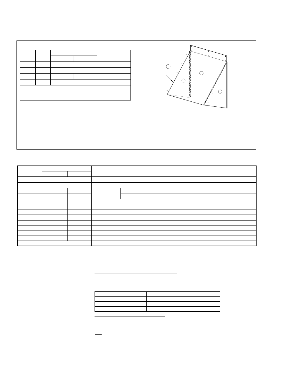
6.2.2 Exhaust Air Hood
FIGURE 11 - Components and Assembly of the Exhaust Hood
Exhaust Hood Components and Installation
Code Qty
P/N
Description
Size 8
Size 12
1
1
260210
Hood Left Side
2
1
260211
Hood Right Side
3
1
261138
261855 Hood Top Cover
4
26
11813
Screws*
* Screws are shipped in hardware bag,
P/N 260354, that
is in the carton with the inlet hood parts. The bag includes
enough screws for both the inlet and exhaust hoods.
Exhaust Hood Assembly and Installation Instructions
1. Undo the exhaust hood component bundle and identify the three parts illustrated above.
2. If the exhaust opening has a shipping cover, remove it.
If the exhaust opening has a factory-installed damper, check damper blade operation.
3. Position one of the hood side panels with the flange out as illustrated. Line the holes up with the holes in the
cabinet. Attach the side panel to the cabinet with the screws provided. Repeat with the opposite side.
4. Position the hood top UNDER the edge of the cabinet top and OVER the installed side panels.
Using six screws, attach the hood top to the cabinet. Attach the top to both sides as illustrated.
2
Right
Side
1
Left
Side
3
Top
Cover
4
Screws
(26 required)
Outside Inlet Air
Hood Assembly and
Installation Instructions
- Steps apply to both
sizes unless noted.
Components of the Inlet Air Hood - (qty) and P/N by Model ZQYRA Size
CODE (See
FIG 13B-D)
(Qty) & P/N by Size
Description
Size 8
Size 12
A
(2) Strips of P/N 103604 Gasket strips are for across top and bottom; length of each is 23” (584mm) .
B
(2) Strips of P/N 103604 Gasket strips are for sides - Size 8, 28-1/2” (724mm) length; Size 12, 32” (812mm) length
C
(1)
262662 (1) 262662 Inlet Hood Top For Top Hood (top with wider flange across the back)
D
(1)
262663 (2) 262663
For Middle and Bottom Hoods
E
(2)
262665 (3) 262664 Inlet Hood Right Side Panel
F
(2)
262667 (3) 262666 Inlet Hood Left Side Panel
G
(2)
262668 (3) 262668 Front Hood Cross Brackets - Length 21-15/16” (557mm) & Width 1-1/16” (27mm)
H
(2)
262669 (3) 262669 Rear Hood Cross Brackets - Length 22-13/16” (579mm) & Width 2-1/16” (52mm)
J
(4)
262671 (6) 262671 Side Filter Bracket
K
(2)
262670 (3) 262670 Filter Access Panel
M
(2)
262673 (3) 262673 Permanent Aluminum Filter, 1x14-1/2x22-1/2
N
N/A
(1)
262672 Front Filler Plate
(107)
11813
Screws (in hardware bag,
P/N 260354, for both the inlet hoods and the exhaust hood)
6.2.3 Inlet Air Hood
Inlet Air Hood Components
1. Identify the hood components from the list above and the assembly illustrations.
2. Prepare the Cabinet Inlet
a) Remove the shipping cover.
b) If the inlet has a factory-installed damper, check the damper for any damage.
(For additional information on the damper, see Paragraph 6.2.4.) If damper
blades are operating properly, remove the screws (listed in table below) holding
the damper frame.
Facing the Inlet Opening
Size 8
Size 12
Across the Top
4 screws
4 screws
Right Side
5 screws
8 screws
Left Side
1 screw
2 screws (in oblong holes)
If the inlet does not have a damper, there are no screws to remove.
c) Determine gasket strip location, clean the surface, and carefully attach each
gasket strip in the order listed.
1st - BOTTOM Gasket Strip (A) - At the corner, measure up from the bottom of
the cabinet:
- Size 8 - 7-1/2” (191mm)
6.0 Mechanical
(cont’d)
6.2 Inlet Air and Exhaust Air Openings (cont’d)
Use of the vertical supply air cover will be determined in Paragraph 6.3.