2 energy recovery (enthalpy) wheel, 3 heat pump (r-410a refrigerant), Figure 18b - heat pump compressor and piping – Reznor ZQYRA Unit Installation Manual User Manual
Page 17
Form I-ZQYRA P/N 260414R5, Page 17
7.4.2 Energy
Recovery (enthalpy)
Wheel
The energy recovery wheel is equipped with a motor and belt drive. When the unit
controller requires energy recovery, the wheel motor responds and rotates the wheel
through both the inlet and return airstreams.
7.4.3 Heat Pump
(R-410A Refrigerant)
Compressor - The heat pump has a digital scroll compressor providing quieter, more
efficient operation. The compressor has high and low pressure switches, a crankcase
heater, a thermistor to protect against too high temperature, and a modulating solenoid
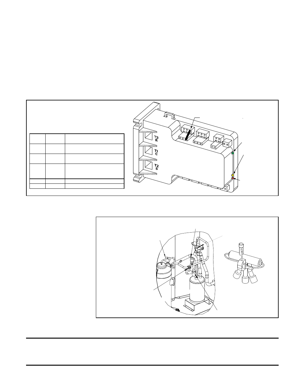
valve for operation. The digital controller in the electrical compartment (See
FIGURES
18A and 19.) is the electronic interface between the compressor and the system con-
troller. The compressor controller is connected to the unit control to provide protection
and diagnostics for compressor operation.
After a compressor shutdown, a two-minute anti-short cycle timer in the compressor
controller delays the compressor restart. The unit controller has a five-minute com-
pressor on/off time. The delay times are concurrent so total delay time is five minutes.
Power Light
(Green LED)
Compressor
Modulating
Solenoid Valve
Energized Light
(Yellow LED)
Alarm Light
(Red LED) - See
Paragraph 10.3.2.
Compressor Digital
Controller for
Modulating Operation
M1
A1 A2
L1 L2
U2
U1
M2
V1 V2
P6
P5 P4
P3 P2
P1
C2
C1
C4
C3
24
VAC
24
COM
T6
T5 T4
T3 T2
T1
560K OHM Resistor
between T1 & T2
FIGURE 18A - Compressor Digital
Controller located in the control
compartment interfaces the
compressor with the unit controller.
LED
Color
LED
State
Indicates
Green Solid
Power (24VAC present at
power terminals)
Green Flashing Anti-short cycle timer is
active
Yellow Solid
Unloader (Solenoid valve
is energized; compressor
capacity is 0.)
Red
Not lit
No abnormal operation alerts
Red
Flashing See Paragraph 10.3.2.
The heat pump compressor and refrigerant piping with reversing valve shown in
FIG-
URE 18B are located directly under the control compartment and are accessed through
the same removable side panel.
Thermistor
Low Pressure Switch (auto
reset) is on the suction line.
High Pressure Switch (manual
reset) is on the discharge line.
Reversing Valve
(enlarged view below)
Compressor
Modulating
Solenoid Valve
Compressor
Accumulator
When the controller calls
for heat, the valve reverses
refrigerant flow.
FIGURE 18B -
Heat Pump
Compressor
and Piping
The scroll compressor also has a belly band crankcase heater which straps around the
bottom half of the compressor. The crankcase heater must be allowed to warm up for
at least 24 hours prior to startup or after an 8-hour power outage.
Crankcase Heater
CAUTION: Crankcase heater must be allowed to warm up for at least 24 hours prior to startup
or after a power outage of eight or more hours. Either turn the unit off with a CN option switch if
available or remove the jumper to break contact between Terminals 3 and 8, BEFORE turning on
power to warm up the crankcase heater.