0 electrical and wiring (cont’d), 5 control wiring (field-installed) (cont’d) – Reznor ZQYRA Unit Installation Manual User Manual
Page 22
Form I-ZQYRA P/N 260414R5, Page 22
7.0 Electrical and Wiring (cont’d)
7.5 Control Wiring (field-installed) (cont’d)
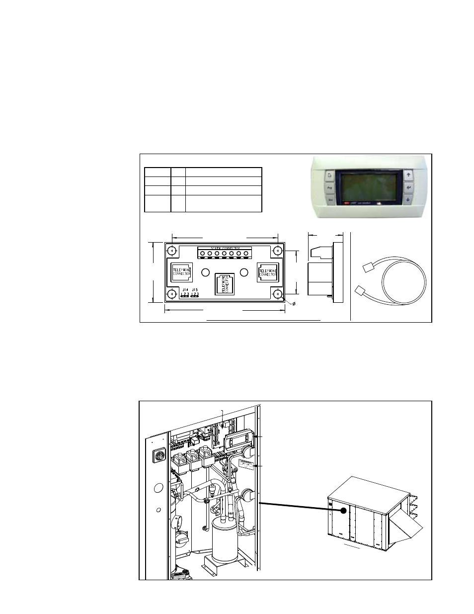
Field-Installed, Remote
Mounted Unit Display,
Option RB5
.219”
(6mm)
1.125”
(29mm)
.91”
(23mm)
3.13” (80mm)
1.56”
(40mm)
(2) Cable Splitter and Signal
Booster Modules, P/N 260735
(2) 6-pin Connection
Cables, P/N 260175
2.75 (70mm)
6
0
A
B
SC
C
Front and Side Views with Dimensions
FIGURE 26 -
Components of Option
RB5, Field-Installed
Remote Display
Component List
P/N Qty Description
260178 1 Unit Display
260175 2 6-pin Connection Cable
260735 2 Cable Splitter and Signal
Booster Module
Unit Display, P/N 260178
The factory-installed display (Paragraph 8.1) allows complete access to unit test fea-
tures, schedules, discharge air setpoints, fan control, alarms, and other unit opera-
tional setpoints. Option RB5 is a second, remote-mounted display that can be field-
installed up to 1500 ft (457M) from the unit allowing the same unit access. To install the
remote-mounted display, follow the illustrated instructions below.
Instructions to field install Option RB5, Remote Mounted Display
Option RB5 is a remote unit interface display that provides the same access as the
unit interface module described in Paragraph 8.1. The remote unit interface module
is shipped separately or loose for field mounting. Field-supplied 22 AWG to 18 AWG
twisted pair wire (EIA 485) and an electrical junction box are required. Follow the
instructions below for setup and installation.
1. Turn power off to the unit (lock the disconnect switch open).
2. Install one Cable Splitter and Signal Booster Module inside the Cabinet
a) Remove the electrical compartment access panel. Position one of the cable
splitter/signal booster modules
(P/N 260735) on the wall of the electrical
compartment as illustrated. Attach it with the screws provided.
FIGURE 27A - Install
one of the cable
splitter and signal
booster modules on
the wall of the electrical
compartment.
Attach cable splitter/cable
booster module for Option
RB5 to the wall of the
control compartment.
Main Controller
Unit Display
Control
Compartment
(Control Side
)