2 specific wiring by control option – Reznor ZQYRA Unit Installation Manual User Manual
Page 19
Form I-ZQYRA P/N 260414R5, Page 19
24V Field Control Wiring Length and Size Requirements
Total Wire Length
Minimum Recommended Wire Size
150 ft
#18 gauge shielded wire
250 ft
#18 gauge shielded wire
350 ft
#14 gauge shielded wire
The manufacturer recommends for optimum temperature control performance that the
analog and digital inputs (CO
2
and air quality sensors) that are connected to the main
controller have a <3% wattage drop and be routed to the unit in one of the following
manners:
1) In separate conduits, isolated from 24 VAC controls and line voltage power to the
unit, OR
2) If the digital sensor wires are to be run in the same conduit as the 24 VAC control
wiring, the CO2, VOC, and display sensor wiring in Options CN7B, CN7C, and
RB5 must be completed using shielded cable and bundled separately from the 24
VAC control wiring. The shield must be drained at the unit and taped on the oppo-
site end.
Comply with the digital control sensor wire gauge and length requirements in the
table below.
Digital Control
Signal Wiring
Recommendations
and Requirements
Maximum
Sensor Wire
Length for less
than 1°F Signal
Error
Wire Gauge
Maximum Sensor Wire Length (Digital Control)
AWG
Feet
Meters
14
800
244
16
500
152
18
310
94
7.5.2 Specific Wiring
by Control Option
Depending on which field-installed control option was ordered, the unit will operate
whenever there is a call for fresh air (ventilation) from that control. Otherwise, the unit
is OFF.
• Option CN5 - Wall-mounted, Manual Start/Stop Switch
• Option CN7A - Time Schedule Clock with Manual On/Off Override Switch
• Option CN7B - CO
2
Sensor with Unit Control Hand/Off/Auto Switch
• Option CN7C - Indoor Air Quality (VOC & CO) with Hand/Off/Auto Switch
• Option CN7D - Occupancy Motion Switch with Manual On/Off Override
Switch
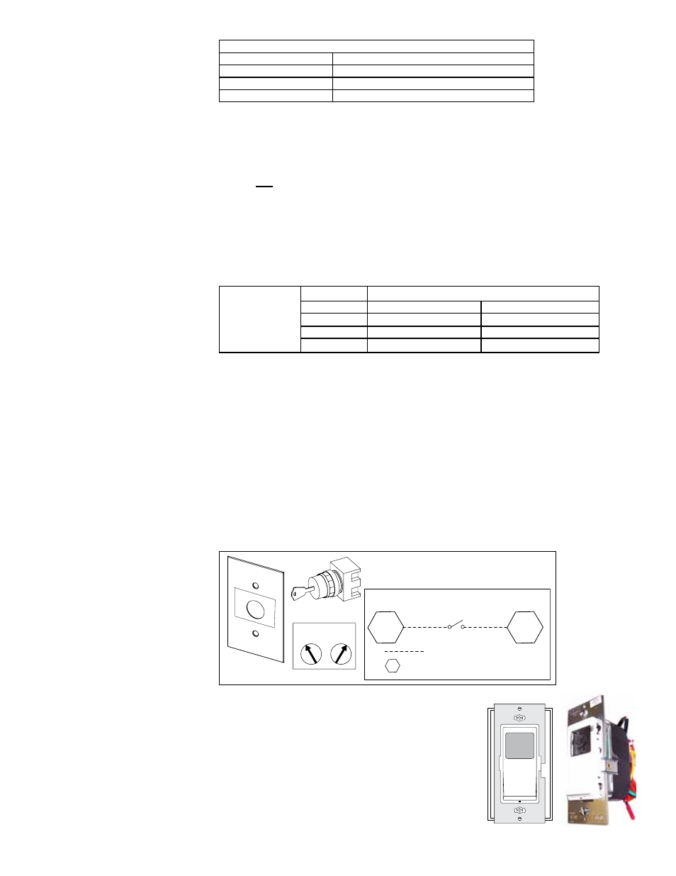
Wall Start/Stop Switch,
Option CN5
The wall-mounted, manual two-position key switch in Option CN5 will start or stop the
unit. Mount the 2-wire, 24V switch in a field-supplied, standard 2 x 4 electrical box.
Install the cover plate. Follow the wiring diagram to run the wires and make the con-
nections. Mount the start/stop switch on the wall.
START
STOP
START
STOP
2 Key Positions
KEY LOCK
POWER SWITCH
CN5
2-Position (start/stop)
Key Switch, P/N 260227
Cover, P/N 260229
Label, P/N 260228
Reference
Components and wiring
information for Option CN5.
8
3
=
field wiring
=
field connection terminal block in the
electrical compartment of the unit
FIGURE 21 - Option
CN5, Start/Stop Wall
Switch and Wiring
Connections
Time Clock Wall Switch,
Option CN7A
The compact wall-mounted time clock with manual
ON/OFF override will start or stop the unit. The
24-hour time clock schedule allows flexible week-
day and weekend start/stop times with a convenient
daylight savings update. A rechargeable battery
maintains the programming in a temporary power
outage.
The unit requires a 2-wire, 120V power
supply, external of the ventilation unit. As shown
in the wiring diagram, a switch relay converts the
time clock 120V output to a set of dry contacts. Two