0 electrical and wiring (cont’d), 5 control wiring (field-installed) (cont’d), 2 specific wiring by control option (cont’d) – Reznor ZQYRA Unit Installation Manual User Manual
Page 20: Sensor, option cn7b, Figure 23 - option cn7b, co, Sensor switch and wiring connections, Time clock wall switch, option cn7a (cont’d), The co, Level (±50 ppm). when in auto, the co
Form I-ZQYRA P/N 260414R5, Page 20
7.0 Electrical and
Wiring (cont’d)
Multi-Voltage Relay Module, P/N 260189, used with
Option CN7A is mounted in the electrical
compartment at the factory; see FIGURE 16, page 16.
Time ClockWall Switch,
Leviton Model VPT24-1P,
P/N 260188
BK
BL
W
O
R
BK
W
Y/R
R
G/Y
(HOT) BK
(NEUT) W
}
115/1/60
LIN
E
PAM-1
TIMER
SWITCH
Y
22
23
BL
8
Multi-voltage
relay
(see below)
3
= field wiring
= field connection terminal block
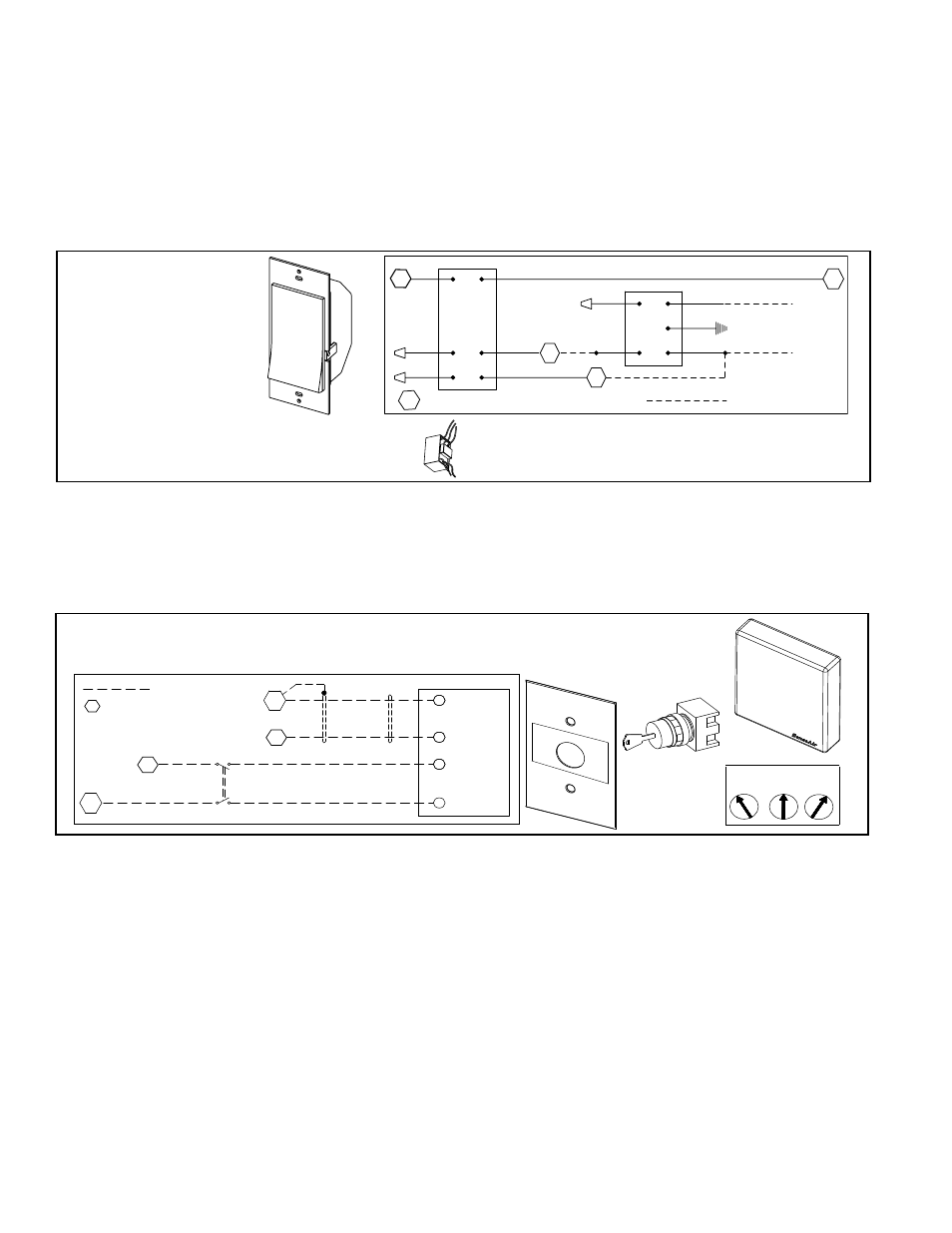
FIGURE 22 -
Option CN7A,
Time Clock
Wall Switch
and Wiring
Connections
CO
2
Sensor, Option
CN7B
The CO
2
sensor with manual HAND/OFF override will start or stop the unit. The infra-
red beam technology provides reliable and accurate sensing of the CO
2
level (±50
ppm). When in AUTO, the CO
2
sensor will activate the unit whenever the carbon diox-
ide rises above the factory default value of 1000 ppm (0-2000 ppm range). The manual
key switch will allow the unit to be directly commanded HAND or OFF, bypassing the
sensor.
FIGURE 23 - Option CN7B, CO
2
Sensor Switch and
Wiring Connections
Follow the sensor manufacturer-provided instructions for mounting the sensor. Install the switch in a field-supplied,
standard 2 x 4 electrical box to be mounted in the wall.
The sensor is powered from the control module 24VAC transformer. Follow the wiring diagram to run the wires and
make the connections. Use shielded 2/c cable for the 0-10V digital signal.
Attach the “HAND/OFF/AUTO” cover plate.
Indoor Air Quality
(VOC and CO) Sensor,
Option CN7C
The volatile organic compound (VOC & CO) sensor with manual HAND/OFF override
will start or stop the unit. When in AUTO, the unit will start whenever the air quality in
the space environment exceeds the VOC level of the setpoint.
This option also provides a three-position keyed, manual switch that is wired to the
digital input. The three position switch provides “auto”, “hand (manual on)” and “off”
modes.
• When the switch is in the AUTO mode, the sensor is powered, the digital start/stop
input is open, and the system monitors the VOC levels.
• When the switch is in HAND mode, the contact is closed and the sensor is
disabled. When the input is closed, the unit is on.
dry contact wires are terminated to controller terminals 3 and 8 which activate the unit
when closed.
Install the time clock in a standard, field-supplied 2 x 4 electrical box to be mounted in
the wall. Provide power to the time clock. Follow the wiring diagram to run the control
wires and make the connections. Add the supplied cover plate. For programming, see
the instruction sheet provided by the manufacturer. Follow the instructions for program-
ming Leviton Model VPT24-1P.
Time Clock Wall Switch, Option CN7A (cont’d)
7.5.2 Specific Wiring by Control Option (cont’d)
7.5 Control Wiring
(field-installed)
(cont’d)
CO2 Sensor,
P/N 234820
Keyed, 3-Position
Wall Switch,
P/N 260230
Cover, P/N 260229
Label, P/N 260231
3 Key Positions
HAND
OFF
AUTO
HAND
AUTO
OFF
Reference
11
SW2
AUTO & HAND
AUTO
SW1
8
SHIELD
2
GROUND
4
SIGNAL
CO2 SENSOR
SHIELD
(OPT. CN7B)
2
POWER
1
GROUND
SWITCH
KEYED
9
3
= field wiring
= field connection terminal
block in the electrical
compartment of the
ventilation unit