Reznor ZQYRA Unit Installation Manual User Manual
Page 23
Form I-ZQYRA P/N 260414R5, Page 23
b) In the electrical compartment, find the unit display and the main controller (See
FIGURE 27A). At the main controller, locate and unplug the 6-pin connection
cable (the cable that connects from the unit display to the controller). Move the
disconnected end of the cable to the module installed in Step 2a) and connect it
to plug “A” (see illustration below).
c) Install one of the new 6-pin connection cables (P/N 260175), connecting one
end to the main controller and the other to plug “S” (see below) on the module
installed in Step 2a).
3. Install the second Cable Splitter/Signal Booster Module at the Remote
Location
a) Determine the desired location for the remote display unit. It can be located up
to 656 feet (200M) from the unit.
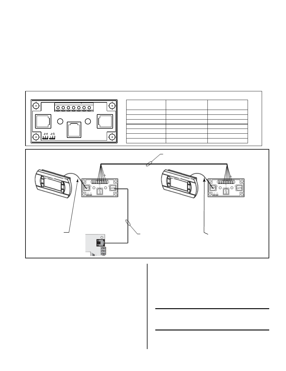
Wiring Connections on Cable Splitter and Signal BoosterModule, P/N 260735
6
0
Plug
A
Screw Terminals
Plug
B
Plug
C
Terminal Screw
Connection
Pin Telephone
Connection
Meaning
0
=
Earth
1
1
+VRL=30 Vdc
2
2
GND
3
3
Rx-/Tx-
4
4
Rx+/Tx+
5 (not used)
5 (not used)
GND
6 (not used)
6 (not used)
+VRL=30 Vdc
FIGURE 27B - Wiring
Connections on Cable
Splitter in Option RB5
Remote-Mounted
Cable Splitter/
Signal Booster
Module
(field-
installed in STEP 3b)
6-pin Wire
Connection Cable
(factory-installed,
moved in STEP 2b)
6-pin Wire
Connection Cable
(field-installed, STEP 2C)
Maximum Length - 1500 ft (457M)
6-Pin Connection on
Main Controller
(factory-installed)
6-pin Wire
Connection Cable
(field-installed,
STEPS 3c, 4a, and 4b)
Field-supplied - 2 sets shielded twisted
pair wire, EIA485, 22 AWG to 18 AWG
Shield
Shield
Unit-Mounted
Display
(factory-installed
in the electrical
compartment)
Remote-Mounted
Display in Option RB5
(field-installed,
STEP 4)
Unit-Mounted
Cable Splitter/
Signal Booster
(field-installed in
STEP 2a)
FIGURE 28 - Wiring Connections for
Installing Option RB5
Using field-supplied
22 AWG to 18 AWG shielded
twisted pair wire (EIA 485), run dedicated wires
from that location to the unit. Two sets of twisted
pair wire are required -- one for the power and one
for communication. The communication wire should
be shielded to prevent noise.
On the cable splitter/signal booster module installed
in Step 2a), connect the shield to screw terminal 0.
Connect the power wires to screw terminals 1 and
2. Connect the communication wires to terminals 3
and 4.
On the cable splitter/signal booster module installed
in Step 2a), connect the power wires to screw
terminals 1 and 2. Connect the communication
wires to terminals 3 and 4.
b) Install the second cable splitter/signal booster
module
(P/N 260735) in a field-supplied junction
box to be recessed behind the remote display.
Connect the shield to screw terminal 0. Connect
the power wires to terminals 1 and 2 and
communication wires to terminals 3 and 4, making
sure that power and communication polarity is
maintained.
CAUTION: Improper wiring can damage
the remote unit interface display as well as
the main system controller.
c) Attach the second 6-pin connection cable (P/N
260175) in the kit to plug “A” on the remote cable
splitter/signal booster module.