0 maintenance and service (cont’d), 2 maintenance procedures (cont’d) – Reznor ZQYRA Unit Installation Manual User Manual
Page 64
Form I-ZQYRA P/N 260414R5, Page 64
WARNING
Weight of the installed segments will cause
the wheel to accelerate in rotation. Failure
to maintain control of the wheel rotation
while re-installing all segments could
cause severe injury to fingers or hand
caught between revolving spokes and the
bearing support beam. Insert the handle of
a hammer or other such tool through the
spokes above or below the bearing support
as a stop to limit rotation of an unbalanced
wheel.
Position one segment opening at the top of the
cassette. Insert a “stop” (see warning above) to hold
the wheel in place. Unlock and open the segment
retaining brackets on both sides of the opening.
Position a clean segment with the imbedded
stiffeners toward the motor side of the wheel.
Holding the segment as vertically as possible and
centered between the spokes, insert the nose of
the segment downward between the hub plates.
Ease the segment down until its outer rim clears the
inside of the wheel rim and press it inward against
the spoke flanges. Close and latch the retaining
brackets. Make sure each retaining bracket is fully
engaged under the catch.
b. Remove the stop and slowly rotate the installed
segment to the bottom of the wheel. Re-insert the
stop and repeat the procedure to put a segment in
the top position. Continue the procedure, balancing
the wheel by installing opposite segments, until all
of the segments are in place.
c. While the wheel cassette is out, follow the
instructions below to check the seals and the drive
components.
d. After all wheel maintenance is complete, position
the wheel supports (See
FIGURE 32.) on the top
and bottom of the cassette and carefully slide all
three pieces back into the cabinet. Being sure the
cassette is positioned properly, replace the blockoff
panel. Re-connect the motor wire.
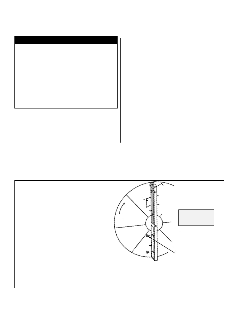
Checking the Wheel
Seals (FIGURE 34)
The seals are on the center support that goes across the diameter of the wheel. There
are two seals on each side of the wheel with one seal on each side of the hub. Seals
are metal strips with insulation on the surface closest to the wheel. The purpose of the
seals is to minimize the transfer of air between the counter flowing airstreams.
After any wheel service and during maintenance, check the seal adjustment. Adjusting
the seals will require a screwdriver and a piece of paper.
Wheel
Rotation
Folded Paper
Feeler Gauge
Adjusting Screws
(Only loosen when adjusting
seal; do not remove.)
Slide seal (shown in gray) toward wheel
until a slight friction on the feeler gauge
is detected when gauge is moved along the
length of a spoke. Repeat with all seals.
Seal
Repeat the same
adjustment procedure
to the two seals on the
other side of the wheel.
Seal
FIGURE 34 - Adjust Seals on the Energy
Recovery Wheel
1. If the wheel has not been removed from the
cabinet, follow steps in
FIGURE 33.
2. Each seal strip has adjustable retaining screws
that allow the insulation to move toward or away
from the wheel. Refer to
the illustration and
follow the instructions below to adjust the
seals.
a) On one seal, loosen the seal retaining screws
just enough to slide the seal strip.
b) Fold the piece of paper to use as a feeler
gauge. Position the folded paper between the
wheel surface and the seal. Turn the wheel so
that the seal is lined up with a segment spoke.
c) Adjust the seal toward the wheel surface and
slide the feeler gauge (folded paper) along the
length of the spoke. When a slight friction is
detected on the feeler gauge (folded paper),
tighten the screws. Recheck the clearance
with the feeler gauge.
d) Repeat the procedure on the other three seals.
3. When the unit is started, start and stop the wheel several
times to verify seal adjustment and to confirm that the
belt is tracking properly on the wheel rim. The belt should
be approximately 1/4” from the outer edge of the rim.
10.0 Maintenance
and Service
(cont’d)
10.2 Maintenance Procedures (cont’d)
10.2.4 Energy Recovery Wheel (cont’d)
Checking Wheel Drive
Components
Instructions (cont’d)
Motor - The motor bearings are pre-lubricated and do not need additional lubrication.
Clean any dirt from the air cooling ports in the motor housing.