0 electrical and wiring (cont’d), 5 control wiring (field-installed) (cont’d) – Reznor ZQYRA Unit Installation Manual User Manual
Page 24
Form I-ZQYRA P/N 260414R5, Page 24
7.5 Control Wiring
(field-installed)
(cont’d)
7.0 Electrical and
Wiring (cont’d)
Instructions to field install Option RB5, Remote Mounted Display (cont’d)
4. Install the Remote Display
a) Remove the back cover of the remote unit interface display (P/N 260178).
Position the back cover over the cable splitter/signal booster module installed in
Step 3b) and feed the 6-pin connection cable out through the hole in the cover
plate. Mount the back cover plate to the wall covering the cable splitter/signal
booster module.
b) Unsnap the face cover from the remote unit interface display. Locate the 6-pin
wire connection and connect the cable from the cable splitter/signal booster
module. Using the screws removed, re-attach the display to the back cover
plate. Snap the display face cover in place.
5. Verify power and communication polarity before re-powering the unit.
6. Turn power on to the unit. Set the Address of the Remote Display.
a) All displays have a factory-set address of 32; therefore, the address of the
remote display must be changed. To access configuration mode on the remote
display, press the
UP , DOWN , and ENTER buttons and hold all three
for at least 5 seconds. The display on the remote unit will be similar to the one
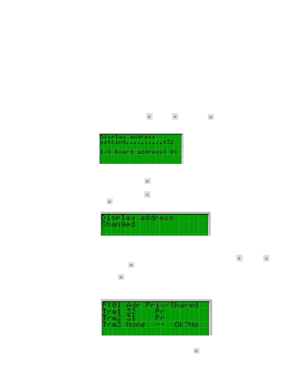
shown below, with the cursor flashing in the top left corner:
b) To change the address of the remote display (“Display address setting”), .follow
these steps.
1) Press the
ENTER button once; the cursor will move to the “Display address
setting” field.
2) Using the
DOWN button, change the display address to 31. Press ENTER
again to confirm the setting. The following screen will be displayed and the
new address will be saved to the permanent memory.
c) The list of terminals associated with main control module is set at the factory and
should not need to be adjusted. If access is needed, the following procedure can
be used.
Access configuration mode on the remote display (press
UP
,
DOWN
,
and
ENTER buttons and hold all three for at least 5 seconds). NOTE: The
I/O Board Address” field should remain at the default setting of “01”. Press the
ENTER button four times to bypass the display address screen and move to
the terminal configuration screen as shown below. This screen tells the controller
what each of the terminal addresses are. The first terminal should be at 32 and
the second terminal will be at 31.
To exit the configuration procedure and save the data, select the “OK?” field, set
“Yes”, and confirm by pressing the
ENTER button.
7. Check the remote display for proper operation.