4 condensate drain – Reznor ZQYRA Unit Installation Manual User Manual
Page 13
Form I-ZQYRA P/N 260414R5, Page 13
6.4 Condensate
Drain
All systems require a condensate drain. A non-corrosive drain pan with a 3/4 Schedule
40 PVC socket adapter fitting is located on the non-control side of the cabinet. When
connecting the drain line, provide a means of disconnecting the line at or near the
cabinet connection to allow for cleaning.
Ensure the system is level before connecting the drain line.
Do not reduce the drain
diameter.
Follow the instructions below to install a trap in the drain. Pitch the drain line at least
1/2" (13mm) for every 10 feet (3M) of horizontal run. Drain lines must not interfere with
drain pan or access panels.
An obstruction in the drain or a poorly designed drain can cause the condensate pan
to over flow. Do not reduce the drain piping diameter. Overflow could result in damage
to the unit and/or the building.
If the installation or local code requires, run drain into a waste water system.
• Duct Sizing - Proper sizing of the supply air ductwork is necessary to ensure a
satisfactory installation. The recognized authority for such information is the Air
Conditioning Contractors Association, 2800 Shirlington Road, Suite 300, Arlington,
VA 22206 (www.acca.org). A manual covering duct sizing in detail may be
purchased directly from them.
• Duct Connections - To minimize sound and vibration transmission, use
flexible duct connections. Ducts must be attached and sealed to provide airtight
connections.
• Return Air Duct/Grill Size - Make certain that return air ducting or grill has a free
area equal to the return duct size connection.
NOTE: Do not reduce
the diameter of the
condensate drain piping.
3/4” PVC is required for
attaching to the drain
connection. See
FIGURE
10, page 9, for drain
location.
Condensate Drain Trap
The design of the drain trap is important. The trap height must account for this static
pressure difference. Maximum negative static can be determined by reading the nega-
tive pressure at the blower inlet and adding .2” w.c. to allow for dirty filters.
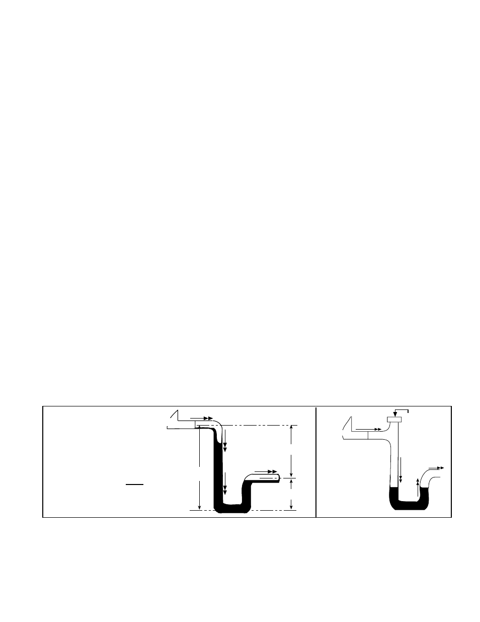
If dimension "B" in
FIGURE 14A is not tall enough, the water seal will not hold, and air
will be drawn through the drain pipe into the system. If the outlet leg of the trap is too
tall, water will back up into the drain pan. As condensate forms during normal opera-
tion, the water level in the trap rises until there is a constant outflow.
FIGURE 14A
illustrates the appropriate dimensions for trapping a negative pressure system.
Improper trap design accounts for some condensate drainage system failures, but
incorrect use and maintenance of condensate drain trap can also cause problems. The
combination of airborne particles and moisture in the air handler can result in algae
formation in the drain pan and trap. The trap must be cleaned regularly to avoid block-
age that can slow or stop water flow, resulting in backup into the system.
If drain has a cleanout opening (
FIGURE 14B), be sure to close the opening after
cleaning.
To prevent air
from entering
always close
the cleanout.
Water Flow
Unit
FIGURE 14B -
Drain Trap
with Cleanout
B
A
A/2
C
L
C
L
C
L
Unit
Water Flow
Water Flow
A = 1" (25mm) for each 1"
(25mm) of maximum
static pressure plus 1"
(25mm)
B = A + A/2
FIGURE 14A -
Condensate Drain Trap
Dimensions
Condensate Drain Use
At the beginning of the cooling and heating season, inspect and clean the conden-
sate drain pan and line. Thoroughly clean dirt, algae, grease, and other contaminants.
Inspect condensate drain pan, trap, and piping; fill trap with water to ensure proper
operation.
Since the heat pump operates year round, more frequent inspections of the conden-
sate drain may be required. Freeze protection of the trap will be required when the
outside temperature is below freezing.