0 controls (cont’d), 4 control points, 5 controller display menus – Reznor ZQYRA Unit Installation Manual User Manual
Page 34: 3 safeties, alarms, and lockouts (cont’d), 2 maintenance alarms (cont’d), Main page (home screen) menus, Summary menu
Form I-ZQYRA P/N 260414R5, Page 34
8.4 Control Points
Small Controller (Carel uPC) - Software Version 1.05
Controller Point
Point Type
Point Maps
DI1
Dry Contact
SA Fan Status (NO)
DI2
Dry Contact
EA Fan Status (NO)
DI3
Dry Contact
Fan Start/Stop (NO)
DI4
Dry Contact
Digital Compressor General Alarm (NO)
DI5
Dry Contact
Shutdown Contact (NC)
DI6
Dry Contact
SA/EA Alarm Contact (NC)
DI7
Dry Contact
Filter Alarm (NO)
B1
0-1 Vdc / 10K Thermister
Space Temperature ??
B2
10K Thermister
Unit Discharge Air Temperature
B3
10K Thermister
Outside Air Temperature
B4
10K Thermister
Energy Wheel Discharge Air Temperature
B5
4-20 mA
Energy Wheel Discharge Air Humidity
B6
0-5 V Ratiometric Pressure
VOC Sensor (0-100% Air Pollution or CO2 Sensor (0-2000
ppm)
B7
0-5 V Ratiometric Pressure
Outdoor Coil Saturated Suction Temperature
NO1
Relay
Fan Contactor
NO2
Relay
Changeover Solenoid Valve
NO3
Relay
Energy Wheel Contactor
NO4
Relay
Electric Preheat Contactor
NO5
Relay
Alarm Contactor
NO6
Relay
Electric Supplement Heat Contactor
NO7
Relay
(For Future Use)
Y1
1-5 Vdc
Compressor Modulation
Y2
0-10 Vdc
SA Fan Speed
Y3
0-10 Vdc
EA Fan Speed
8.5 Controller
Display Menus
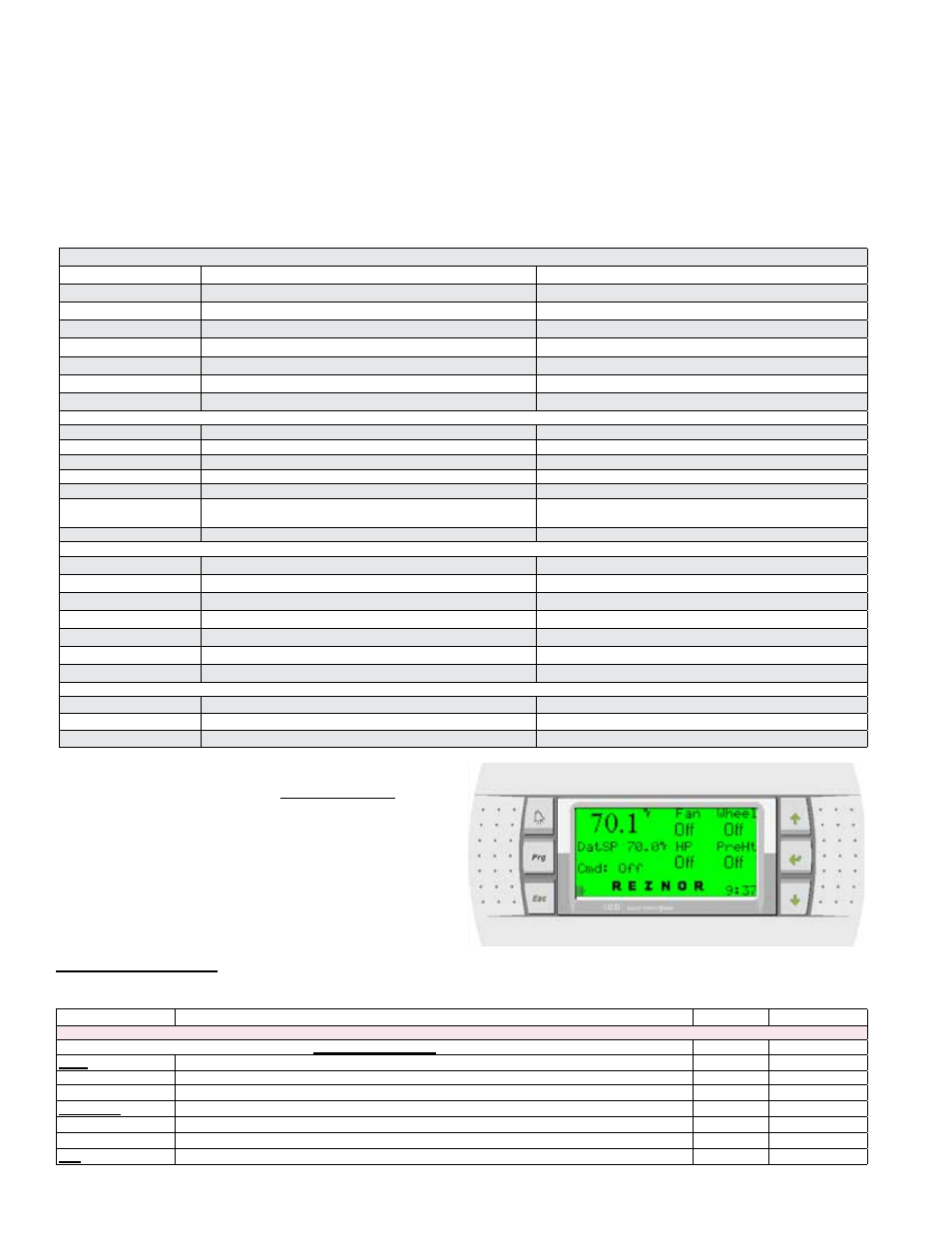
1. MAIN PAGE
(Home
Screen)
MENUS
Control Display Description
Range
Factory Default
Page 1:
- - Summary Menu - -
Unit:
Current status of Supply and Exhaust Air Fan
On Unit is commanded ON and there is a status “ON” for both fans.
Off Unit is OFF.
ER Wheel:
Current status of Energy Recovery Wheel
On Energy Recovery Wheel is commanded ON.
Off Energy Recovery Wheel is commanded OFF.
HP:
Current status of the Heat Pump
2. SUMMARY MENU
The Summary Menu is accessed by pressing the up or down arrows (buttons). To start at the
top of the selections, press the down arrow. To start at the bottom of the Summary Menu, press
the up arrow.
alarm condition. Once the alarm condition is corrected (switch opens), the alarm will
automatically clear and be logged.
Run Time Alarms - The system has the ability to monitor the individual components
and create a specific alarm based on operational run times. These alarms are disabled
by default and can easily be enabled through the unit interface under the “Service”/”Run
Times” menus. Run time maintenance alarms are included for fans, energy recovery
wheel, heat pump, preheat, and filters.
8.3 Safeties, Alarms,
and Lockouts
(cont’d)
8.0 Controls
(cont’d)
8.3.2 Maintenance Alarms (cont’d)