0 startup (cont’d) – Reznor ZQYRA Unit Installation Manual User Manual
Page 60
Form I-ZQYRA P/N 260414R5, Page 60
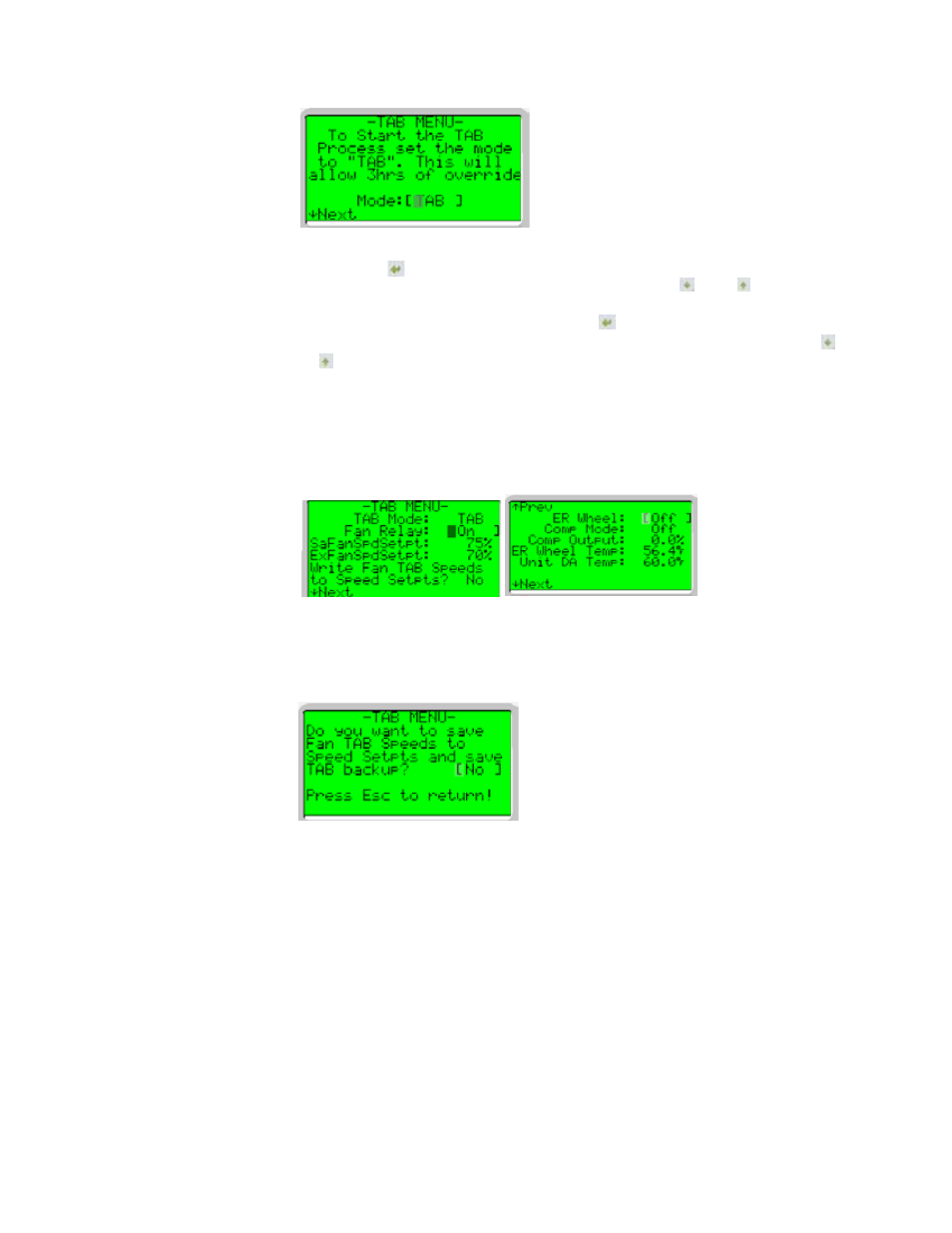
5. In the TAB Menu, the brackets should be on the Mode [TAB setpoint]. Press the
Enter button to select the mode setpoint. This will move the blinking curser off
of the bracket and over to the setpoint. Press the down or up arrow button to
change from the “Off” mode to the “TAB” Mode. Once the setpoint is adjusted to
the desired position, press the Enter button to accept the new setpoint.
Back in TAB mode, additional menus will be available by pressing the down or
up arrow button.
6. In addition to setting the fan speeds and compressor modulation, you will now be
able to enable the fans, wheel, and compressor. (
NOTE: Until you write the new
TAB Speeds to Speed Setpoint, the values are temporary and will be reset to pre-
vious values upon a restart. Also, there is a three-hour time limit on TAB Mode,
and if still in TAB Mode after three hours, the unit will automatically return to Auto
Mode.)
7. Once the “Test and Balance” is complete, select [Write Fan TAB Setpoints to
Speed Setpoint] and set to “YES”. This will move the current TAB fan setpoints
over to the fan permanent setpoints and also create a backup copy of the current
TAB setpoints. (
NOTE: Pressing the ESC button while in this menu will bring up
the following menu to also allow you to save the setpoints.
9.3.2 Measure Supply
and Exhaust Airflow
Pressure Drops
To determine the fan speeds to be set in Paragraph 9.3.1 or 9.3.3, use a manometer to
measure the pressure drops in both the supply airflow and the exhaust airflow.
1. First, measure the supply side. Open the electrical compartment access panel
(See
FIGURE 16, page 16.) and locate the two air proving switches. Determine
which switch is for the supply air side and disconnect both pieces of tubing and
connect them to the manometer.
2. Operate the unit in Manual Test Mode. Record the value shown on the
manometer; this is the supply side pressure drop.
3. From the chart on page 61, convert the pressure drop to CFM. Use this CFM
when setting the fan speed in the TAB Menu (Paragraph 9.3.1).
4. Disconnect both pieces of tubing from the manometer. Reconnect the clear tubing
to the low side of the air proving switch. Do not reconnect the yellow (or with black
tape) tubing to the air proving switch. The air differential of those tubings might
cause an alarm from the controller. Secure the unconnected piece of tubing to the
cabinet.
5. Repeat the process with the other air proving switch to measure the pressure drop
in the exhaust airflow.
9.0 Startup
(cont’d)
9.3 Setting Fans to Test and Balance Airflow (cont’d)
9.3.1 Setting Fan Speeds Using the TAB Menu (cont’d)