0 startup, 1 preparation and startup requirements, 2 test mode control – Reznor ZQYRA Unit Installation Manual User Manual
Page 57
Form I-ZQYRA P/N 260414R5, Page 57
8.8 Dirty Filter
Alarm, Option
BE18 (outside
air filters only)
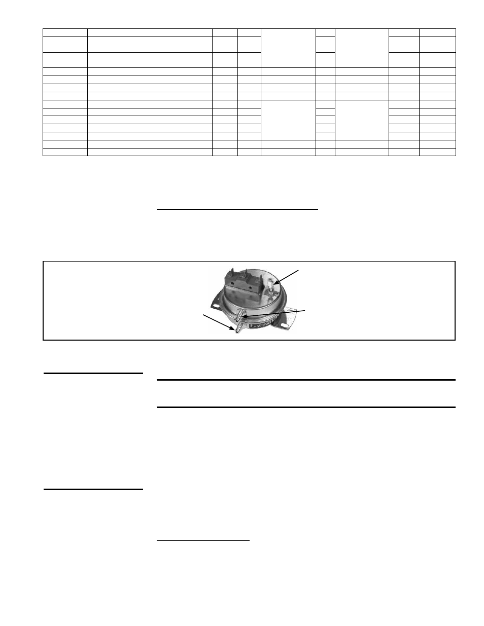
Dirty Filter Switch, P/N 105507
(must be set prior to continuous
operation)
Set screw (on front of switch)
must be manually adjusted after
the system is in operation.
Negative pressure connection is
toward the “front or top” of the
switch (senses blower side of filters)
Positive pressure connection is
toward the “back or bottom” of the
switch (senses air inlet side of filters)
Dirty Filter Switch - If there is a dirty filter alarm, there is a dirty filter switch in the unit.
(See
FIGURE 16, page 16). After the unit is started, before continuous operation, the
dirty filter switch must be set.
Instructions for Setting Dirty Filter Switch - With clean filters in place; all doors
closed (except electrical compartment); and the fan operating, increase the pressure
setting by adjusting the setscrew on the switch clockwise until the filter light is ener-
gized or the screw is bottomed out. At that point, adjust the setscrew three full turns
counter clockwise or until the screw is top ended. At that setpoint, the filter light will be
activated at approximately 50% filter blockage.
TestMode
Unit in Test Mode (General)
R
-
nvoAlmStat1
(cont’d)
Bit 11
Snvt_state
(cont’d)
-
-
RestartAlm
System in restart Mode.System will auto
restart after 60 mins.
R
-
Bit 12
-
-
ShutdnAlm
System in Shutdown Mode. Manual Restart
Required.
R
-
Bit 13
-
-
RstPhtRts
Reset PreHt Runtimes
R/W
30
nviRstPhtRts
-
SNVT_Switch
-
-
RstFanRts
Reset Fan Runtimes
R/W
31
nviRstFanRts
-
SNVT_Switch
-
-
RstCompRts
Reset Comp Runtimes
R/W
32
nviRstCompRts
-
SNVT_Switch
-
-
RstErwRts
Reset ERW Runtimes
R/W
34
nviRstErwRts
-
SNVT_Switch
-
-
FanHrsAlm
Fan run hours alarm (General)
R
-
nvoRtmAlmStat
Bit 0
Snvt_state
-
-
CompHrsAlm Compressor run hours alarm (General)
R
-
Bit 1
-
-
ErwHrsAlm
Wheel run hours alarm (General)
R
-
Bit 2
-
-
PhtHrsAlm
Preheat run hours alarm (General)
R
-
Bit 3
-
-
FiltHrsAlm
Filter run hours alarm (General)
R
-
Bit 4
-
-
BAS_Shtdwn BAS Unit Shutdown
R/W
40
nviBAS_Shtdwn
-
SNVT_Switch
BAS_AlmRst BAS Alarm Reset
R/W
41
nviBAS_AlmRst
-
SNVT_Switch
9.0 Startup
9.1 Preparation and Startup Requirements
See
APPENDIX, page 71, for a single-page startup check form.
IMPORTANT: Failure to maintain, misuse of the unit, or
wrong startup procedures will void the warranty
Before actual startup, become familiar with the applicable control information in Para-
graph 8.0 and test mode and fan setting procedures in Paragraphs 9.2 and 9.3.
Perform all of the preparation checks on the startup form (page 71). On startup, be pre-
pared to check compressor rotation to verify correct 3-phase wiring connection (Para-
graph 7.1), and to set the fan speeds (Paragraph 9.3).
NOTE: If installation includes
an optional remote display, be sure to follow the instructions in Paragraph 7.5 (or the
control instruction sheet) to reset the display address.
9.2 Test Mode Control
Under the Service Menu (see pages 37-38), there is an automatic and a manual test
mode that allows the user to test each component of the system. There is a three-hour
limit on the manual test mode, and the system will automatically reset back to normal
after the elapsed time.
CAUTION: Check
compressor
rotation to verify
correct phasing.
DO NOT use fan
rotation to check
phasing. ECM
fans cannot run
backwards.
The automatic test mode is used to demonstrate the operation of the unit. There is a
single adjustable timer (2 minute default) that can be used to set the time on how long
each component runs. In auto test mode, the unit will turn on the fans, then the wheel,
then the heat pump, and finally the preheat. The heat pump will first start in the cooling
mode and will modulate from the minimum to 30%. The heat pump will then stop and
restart in the heating mode and modulate from the minimum position to 30% capacity.