0 electrical connections and wiring (cont’d), 3 electrical compartment, 4 electrical components – Reznor ZQYRA Unit Installation Manual User Manual
Page 16: 1 fan motors, Figure 16 - control locations, Locations of components, Control compartment with access panel removed
Form I-ZQYRA P/N 260414R5, Page 16
FIGURE 16 -
Control
Locations
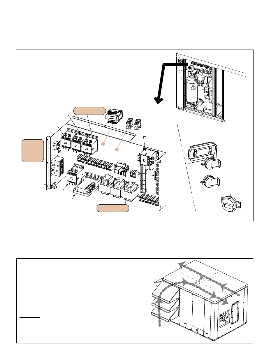
7.3 Electrical
Compartment
Locations of Components
Remove the electrical compartment access panel to view the controls and compressor
as illustrated in
FIGURE 16. Some components in the electrical compartment are com-
mon and some vary by options selected.
7.0 Electrical Connections and Wiring (cont’d)
7.4.1 Fan Motors
The supply and exhaust fans are centrifugal, backward curve fans with integral elec-
tronically commutated motors (ECM) that are directly controlled by the unit interface
control. The unit uses a portion of the outside intake air as part of the return airflow as
shown in
FIGURE 17.
At startup, the speed of each fan must be set. See the instructions in Paragraph 9.3
7.4 Electrical
Components
FIGURE 17 - Diagram showing Airflow through the Unit
Ou
tsi
de
Air Inlet
Exhaust
Air
Supply
Air
Return
Air
WHEEL
NOTE: If installing this ventilation unit
indoors, exhaust and supply airflow will be
double. Ductwork and louvers must be sized
accordingly.
(Size 8 - CFM Range is 500-1100;
Size 12 - CFM Range is 900-1500)
Example: A Model ZQYRA installed indoors
operating at 1500 cfm will require supply and
exhaust ductwork sized for 3000 cfm.
Option BE18
Dirty Filter
Switch
Air Proving Switch
(exhaust side),
P/N 197031 set
at 0.35” w.c.
Air Proving Switch
(supply side),
P/N 197031 set
at 0.35” w.c.
Supply &
Exhaust Fan
Overload Relays
Contactor (optional
electric preheat)
Contactor
(wheel)
Contactor (fans)
Multi Voltage
Relay Module
(time
schedule
clock,
Opt CN7A)
Distribution
Blocks -
A, B, and C
Contactor
(heat pump)
Grounding
Lug
Digital Controller
(Compressor)
Control Transformer
(damper motor)
Control
Transformers
Unit Controller
(NOTE: If ordered
with a BACnet®
or LONworks®
communication
card, it is located
on the controller;
see Paragraph 8.7.)
Field
Connection
Terminal
Blocks
Display
Module
Terminal Blocks
Transformer
(Size 8, 460V)
Contactor
(supplemental
heating element)
Relay
(damper motor)
Controls on either the side or
back wall of the Control
Compartment
Electrical
Panel
Control Compartment
with Access Panel
Removed