0 controls (cont’d), 2 sequence of operation – Reznor ZQYRA Unit Installation Manual User Manual
Page 26
Form I-ZQYRA P/N 260414R5, Page 26
8.2 Sequence of Operation
NOTE: See Paragraph
7.5 for control wiring
details.
Supply and Exhaust Fan Start/Stop Control
Upon a start command, the unit begins the following sequence:
•
Startup is displayed in the Mode status.
•
Factory installed optional outside air damper is energized (damper opens).
•
The supply fan and exhaust fan are started and slowly ramp up to their speed
setpoints. The fan with the highest setpoint starts ramping first to help maintain the
desired pressure condition.
•
Wheel starts 30 seconds after the fans.
•
Heat pump starts 120 seconds after the wheel (if needed per sequence).
During the “ON” mode, the supply fan runs continuously. There is an air proving switch
for each fan that indicates proof of fan operation. The supply fan is subject to all safety
devices to be allowed to run: duct high limit switches, fire alarm relays, smoke detec-
tors, low temperature limits, etc. See the Unit Occupancy Control Options (below) for
sequences and configuration options. The unit is shipped with one of the following
factory-supplied, hardwired switches:
•
Manual On/Off Switch – Option CN5
•
Wall mounted Time Clock with manual On/Off Override – Option CN7A
•
CO2 Sensor with Hand/Off/Auto Switch – Option CN7B
•
Indoor Air Quality (VOC) & CO with Hand/Off/Auto Switch – Option CN7C
•
Occupancy Motion Sensor with Manual On/Off Override – Option CN7D
Unit Occupancy Control Options by Controller Setting TYPE
The unit is shipped preconfigured to the ordered CN option but can be configured in the
field to meet several possible sequence configurations. There are eight pre¬configured
occupancy control options available. When setting the occupancy type, all required
setpoints are available in the occupancy menu after setting the type. Adjustable set-
points are shown in the sequence below by the [ ] symbol around them. The [ ] symbol
also defines the default setting. See the example below for the screen shots and con-
figuration menus. The following sequence defines each type and the options available
under that configuration. The unit occupancy control options can be accessed under
the “Occ Config Menu” located under the main menus
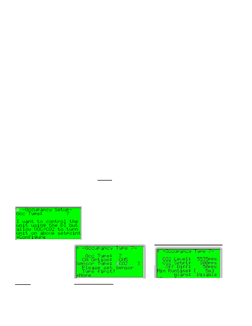
Example 1: TYPE 7 - I want to control the unit using a Digital Input (DI-3) but allow
the VOC or CO2 sensor to override DI when levels are above setpoint. See Type 7,
Occupancy Control Option, page 28, for specific sequence of operation. Once Occ
Type is set, pressing the down arrow will move you to the specific occupancy type
configuration screen.
Required Setpoint Settings: Occupancy - Type 7
CN Options -
CN5
Sensor Type -
[C02] or VOC
CO2 or VOC Level -
Current Reading
CO2 or VOC Setpoints -
[800] / 60
CO2 or VOC Off Diff -
[50] / 15
Min Runtime:
[5 min]
Alarm -
Enable or [Disable]
8.0 Controls
(cont’d)
TYPE 1 - I want to
control the unit using a
Manual On/Off Switch.
Control Option CN5, “Manual On/Off Switch”, offers basic on/off control of the unit
using a wall-mounted switch.
Sequence: This option provides a keyed manual switch that is wired to the digital
input. When the input is closed and when the input is open, the unit is off.
Required Setpoint Settings: Occupancy - Type 1
CN Option -
CN5