Haltech E8 User Manual
Page 95
Haltech E11/E8 Instruction Manual
Figure 99
Staged Injection Angle Split Map
This map only applies to Staged injection for rotary engines. When piston mode is used, the auxiliary
injectors are pulsed at a fixed angle.
When staged fuel injection is enabled, the secondary injectors are often mounted further up the intake
manifold tract. In order to tune the injection timing of the secondary injectors, it is desirable to fire them
slightly ahead of the primary injectors. This map defines the timing split between the primary and
secondary injectors. That is, a split angle of zero degrees will fire the secondary injectors at the same
angle as the primary injectors. A value of 10 degrees in this map will cause the secondary injectors to fire
10 degrees after the primary injectors have fired.
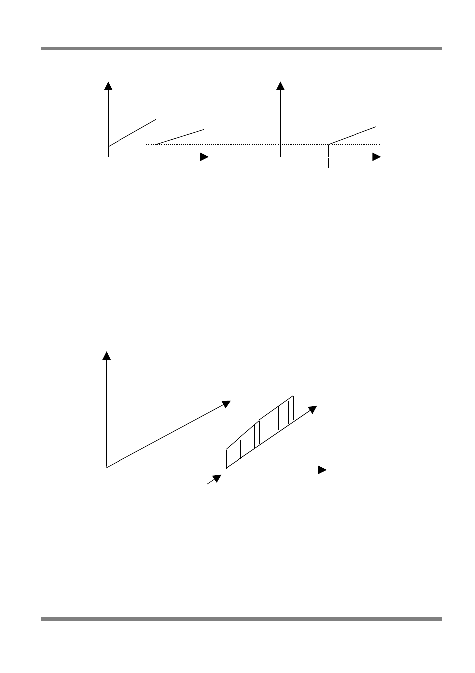
Staged Injection Map
The Staged Injection Map is a 32 bar map that goes across RPM. The bars in this map are additional load
bars that are used in the interpolation on the way down from loads above the staging bar to loads below
the staging bar.
Figure 100
When setting up for staged injection, there is a discrete point at which the injection times must cross over
when the secondary set of injectors turn on. In order to maintain steady mixtures, an additional load bar
must be inserted for every RPM range, at the point where the staging injectors start. This is to allow the
linear interpolation to calculate the correct fuel requirements when crossing the staging bar from low to
high loads and when crossing from high to low loads.
Copyright © Haltech 2008
Page: 95
Injection
Time
Load
RPM
Staged Injection
Map
Staging Bar
Load
Secondary Injectors
Injection
Time
Load
Primary
Injectors
Injection
Time
Staging Bar
Staging Bar