Haltech E8 User Manual
Page 66
Haltech E11/E8 Instruction Manual
To use the TCC function, you must have the following:
A square wave signal road speed indicator whose frequency is proportional to road speed. (This may
require a reluctor adaptor for signal conditioning.)
Access to the wiring of the torque converter lockup solenoid and 4th gear/over-temp switch
Wire the TCC solenoid to the appropriate output line on the output connector, and, if it is available, the 4th
gear/over-temp signal to the appropriately configured Input. The 4th gear/over-temp signal must be a pull-
to-ground style signal.
To determine vehicle speed, a square wave signal must be applied to the road speed input connector.
This connector possesses ground and 12 volt signals for powering a Hall effect or optical sensor. A
magnetic or reluctor type signal is incompatible, and you will need to convert the output from this style of
pickup to a square wave.
Once the wiring is complete, run the ECU software in ONLINE mode and Options->Output Options page.
The parameter Road Speed Value must be set with the number of pulses expected per kilometre. If you
are unsure of the exact value for this parameter, enter an approximate number and check against the
vehicle's speedometer. Adjust the Road Speed Value until the road speed displayed on the Engine Data
Page and the actual vehicle speed agree.
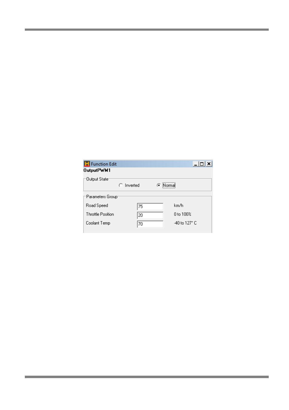
Figure 72 - Torque Converter Control Output
•
Road Speed - The TCC output activates when the road speed exceeds this value.
•
TPS - The TCC output activates when the TPS is less than this value.
•
Coolant Temp - The TCC output activates when the coolant temperature exceeds this value.
When all the above conditions are met, the TCC output activates and locks the torque converter. It is
advisable to never engage the lockup below 60 kph (40 mph).
Turbo Timer
The turbo timer is used to help cool the turbo bearing by running the engine at idle for a short period after
driving. If the engine is switch back to the ignition position whilst the car is running off the turbo timer, then
all the timers get reset.
Care should be taken to make sure the relays are wired correctly, and that an over-ride switch has been
fitted to allow the engine to be switched off manually while the turbo timer is active. See the figure below
for the correct way to wire this output. The ECU detects if the ignition switch has been turned off via the
Auxiliary Input. Therefore, the Auxiliary Input Function must be selected as Turbo Timer Input in the Digital
Inputs page.
Page: 66
Copyright © Haltech 2008